





Selecting the Right Pressure Relief Device for Transformers
Time:2026-09-16 18:05:55 Author:zhongbei Click:120
Transformer tank rupture from internal fault pressure represents one of the most dangerous failure modes in power systems. The explosive energy released when a tank fails catastrophically threatens personnel safety, destroys adjacent equipment, and creates environmental contamination from discharged oil. The pressure relief device is the last line of defense against this scenario—designed to open before tank structural limits are reached, releasing fault gases and preventing rupture. Yet selecting the wrong pressure relief device creates its own problems: a device that operates at too low a pressure causes nuisance trips during normal thermal cycling, while one that operates too close to tank structural limits may fail to prevent rupture when needed. This article provides the technical framework for making selection decisions that protect equipment and personnel without creating operational problems.
Understanding Pressure Relief Device Function
The fundamental purpose of a pressure relief device is to limit tank pressure during internal faults to levels below the tank structural design limit. When internal arcing or rapid gas generation produces pressure peaks that exceed the tank design margin, the PRD opens to release gases and arrest the pressure rise before structural failure occurs.
However, transformers experience normal pressure variations during routine thermal cycling. Oil expands and contracts as temperature changes with load and ambient conditions. If a PRD operates during normal thermal cycles, the resulting oil loss and maintenance burden create operational problems. The selection challenge is to set the operating pressure high enough to avoid normal cycling operation while low enough to open before tank rupture during actual fault conditions.
The pressure margin between normal operating pressure and PRD operating pressure is called the operating margin. This margin must accommodate normal pressure peaks from thermal expansion, load changes, and ambient temperature variations. Typical design practice specifies PRD set pressure at 25 to 40 percent above the maximum normal operating pressure observed during worst-case operating conditions.
Types of Pressure Relief Devices
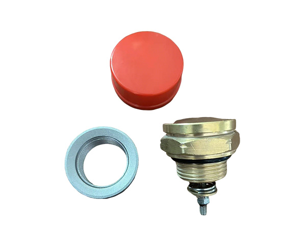
Pressure relief devices for transformers fall into two primary categories—rupture diaphragms and spring-loaded valves—each with distinct operating characteristics and maintenance requirements.
Rupture diaphragm devices use a membrane material, typically silicone rubber coated fabric or metal foil, that seals the tank opening until pressure exceeds the design limit. When the set pressure is reached, the diaphragm ruptures, providing a full-bore discharge opening. Once ruptured, the diaphragm cannot reseal—oil continues to flow until the transformer is de-energized and the diaphragm is replaced. Diaphragm devices are simple, have no moving parts that could stick, and provide very fast response to pressure transients. The single-operation limitation is acceptable for fault conditions that should be infrequent events.
Spring-loaded valve devices use a spring-loaded poppet that lifts from its seat when pressure exceeds the spring force. Many spring-loaded designs reseal automatically when pressure returns to normal levels, making them suitable for conditions where minor pressure excursions may occur without actual faults. The moving mechanism introduces potential failure modes—spring relaxation, mechanism binding, seal degradation—but the reseal capability reduces oil loss from transient operations. Spring-loaded devices are more expensive than diaphragms and require more maintenance to ensure mechanism freedom.
Set Pressure Determination
Selecting the correct set pressure for a pressure relief device requires balancing protection requirements against normal operating conditions. The determination starts with understanding the tank structural design limits and normal operating pressure range.
Transformer tanks are designed to withstand specific internal pressures—typically 0.5 to 1.0 bar above atmospheric pressure for distribution transformers, with larger substation transformers sometimes designed to higher pressures. The tank design pressure establishes the upper limit that must never be exceeded. The PRD set pressure must be selected below this design pressure to provide operating margin for the device to open before rupture occurs.
Normal operating pressure depends on the transformer temperature profile and the conservator tank sizing. Calculate the maximum normal pressure by determining the maximum oil temperature during worst-case loading conditions, computing the oil volume expansion, and calculating the resulting pressure in the conservator system. Include pressure contributions from pump head if forced circulation is employed. The PRD set pressure must exceed this maximum normal pressure by an adequate margin—typically 25 to 40 percent—to prevent nuisance operation during thermal cycling.
For transformers without conservator tanks—sealed units and gas-blanketed designs—the pressure dynamics differ, but the same principles apply: set the PRD at a pressure that exceeds any normal operating pressure while remaining below tank structural limits.
Sizing Flow Capacity
Beyond set pressure, the pressure relief device must have adequate flow capacity to limit pressure rise during fault conditions. A device that opens at the correct pressure but cannot flow enough gas to arrest the pressure rise provides inadequate protection.
Flow capacity sizing follows calculations based on the maximum gas generation rate during fault conditions. Arcing faults can generate gas at rates of 100 to 500 liters per second depending on fault current and arcing duration. The PRD must flow this gas volume while maintaining tank pressure below the design limit.
Manufacturer flow capacity data for specific PRD models enables selection based on calculated requirements. Verify that the selected PRD flow capacity exceeds the calculated maximum fault gas generation rate with adequate margin—typically a safety factor of 2 or more is applied. Undersized PRDs may open but cannot flow enough gas to prevent tank pressure from exceeding design limits.
For large transformers or those with high fault current contributions, multiple PRD devices may be required to achieve adequate flow capacity. Position devices to ensure even pressure relief across the tank and to address pressure gradients that develop during rapid gas generation events.
Compliance With Standards and Regulations
Standards and regulations impose specific requirements on pressure relief device selection and installation that must be incorporated into the selection process.
IEC 60076-3 establishes dielectric test requirements including pressure withstand requirements for power transformers. The standard specifies that transformers must withstand test pressures without permanent deformation, establishing the tank design pressure baseline. PRDs must be selected with set pressures that ensure operation before this pressure is reached during actual fault conditions.
NFPA 70 Article 450 addresses transformer installation requirements including pressure relief provisions. For transformers installed indoors or in areas where tank rupture consequences are severe, codes may require specific PRD types or additional pressure relief provisions. Review applicable codes early in the selection process to ensure that selected devices meet regulatory requirements.
Insurance requirements and utility interconnection standards may impose additional requirements beyond the base standards. Coordinate with insurance carriers and utility engineers to ensure that PRD specifications meet all applicable requirements for the specific installation location.
Environmental and Safety Considerations
The consequences of pressure relief device operation extend beyond the transformer itself. Oil spray, fire risk, and environmental contamination create safety and environmental hazards that influence selection and installation decisions.
Discharge direction affects the hazards created by PRD operation. Devices that discharge oil downward toward the ground create different hazards than those discharging upward or horizontally. Upward discharge spreads oil over a wider area, increasing fire risk but reducing immediate ground contamination. Downward discharge concentrates oil in a smaller area. Specify discharge direction based on site-specific conditions and safety assessments.
Fire suppression provisions may be required when transformers are installed in areas where PRD discharge could ignite. Oil spray from PRD operation in the presence of ignition sources creates significant fire hazards. Evaluate fire suppression requirements based on transformer location, adjacent equipment, and applicable fire codes.
Oil containment systems capture discharged oil and prevent environmental contamination. Containment design must account for the volume and flow rate of oil discharged during PRD operation. The containment system capacity should equal or exceed the total oil volume in the transformer conservator and a portion of the main tank oil, assuming complete discharge is possible.
Installation and Integration With Protection Systems
The selected pressure relief device must integrate properly with the transformer protection scheme and the overall substation protection philosophy.
Alarm contacts on the PRD provide electrical indication when the device operates, initiating transformer trip and alarm sequences. Specify alarm contact configurations that match the protection system input requirements—normally open versus normally closed contacts, voltage and current ratings compatible with the protection relay inputs. Test alarm contact operation during commissioning and periodically during maintenance.
Integration with transformer differential protection and sudden pressure relays ensures that internal faults are cleared quickly after the PRD operates. Coordinate PRD alarm with protection relay settings so that fault clearing occurs promptly after the first indication of internal fault. Delayed fault clearing allows fault energy to continue gas generation, potentially exceeding PRD flow capacity.
Position the PRD at the highest point of the transformer tank where gases accumulate during fault conditions. The location should be accessible for inspection and maintenance while protected from physical damage and environmental contamination that could affect operation.
Frequently Asked Questions
Can a pressure relief device replace sudden pressure relay protection?
No. The PRD and sudden pressure relay serve different functions and complement each other. Sudden pressure relays detect rapid pressure rises from internal faults and trip the transformer before significant gas accumulates. PRDs provide overpressure protection if pressure does exceed design limits. Both devices should be installed on transformers where the consequences of tank rupture justify the investment.
What happens if the PRD set pressure is too close to normal operating pressure?
A set pressure too close to normal operating pressure causes nuisance operation during routine thermal cycling, particularly during heavy load periods or high ambient temperatures. Each nuisance operation results in oil loss and requires PRD inspection and reset. More significantly, the operating margin between normal pressure and set pressure becomes insufficient to accommodate unexpected pressure peaks, increasing the risk of tank rupture if a fault occurs.
Should I specify a resealing or non-resealing PRD?
Non-resealing diaphragm devices are preferred for most applications because they provide the fastest response and the most reliable operation. The requirement to replace the diaphragm after any operation forces investigation of the cause, ensuring that underlying faults are identified. Resealing valves may be appropriate for applications where minor pressure excursions are expected and oil loss from nuisance operation is unacceptable.
How do I determine if a transformer needs multiple PRDs?
Multiple PRDs are required when the calculated fault gas generation rate exceeds the flow capacity of a single device, when transformer geometry creates pressure gradients that single-point relief cannot address, or when redundancy is required for critical transformers. Manufacturer guidelines and fault current calculations determine when multiple devices are necessary.
What maintenance is required for pressure relief devices?
Regular visual inspection verifies that the device is in the unoperated condition, that discharge paths are clear, and that there are no signs of oil leakage. Periodic set pressure testing confirms that the operating pressure remains within specification. Alarm contact testing verifies electrical operation. Documentation of all inspections and tests supports reliability analysis and regulatory compliance demonstrations.
Conclusion
Selecting the right pressure relief device for transformers requires integrating protection requirements, tank design limits, normal operating conditions, and regulatory requirements into a coherent specification. The decision framework outlined—understanding device function, evaluating device types, determining set pressure, sizing flow capacity, and ensuring compliance—produces selection decisions that provide reliable overpressure protection without nuisance operation. For industrial facilities and utility operations where transformer failure carries significant safety and financial consequences, investing the engineering effort in proper PRD selection pays returns through reduced catastrophic failure risk and improved overall transformer fleet reliability.
References
IEC 60076-3:2018, "Power Transformers – Part 3: Insulation Levels, Dielectric Tests and External Clearances," International Electrotechnical Commission.
IEEE Std C57.12.00-2015, "Standard for General Requirements for Liquid-Immersed Distribution, Power, and Regulating Transformers," IEEE Power & Energy Society.
NFPA 70: National Electrical Code, Article 450, National Fire Protection Association, 2023.
CIGRE Working Group A2.37, "Transformer Reliability Survey," Technical Brochure 542, 2015.
MORE
-
Dry Type Transformer Cooling Methods Explained
2026-09-22
-
Selecting the Right Pressure Relief Device for Transformers
2026-09-16
-
Mechanical vs Magnetic Oil Level Indicators for Transformers
2026-09-16
-
How DIN Standard Bushings Meet International Requirements
2026-09-16
-
Choosing Transformer Copper Terminal Stud Specifications
2026-09-16