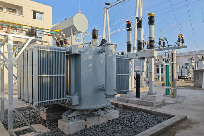
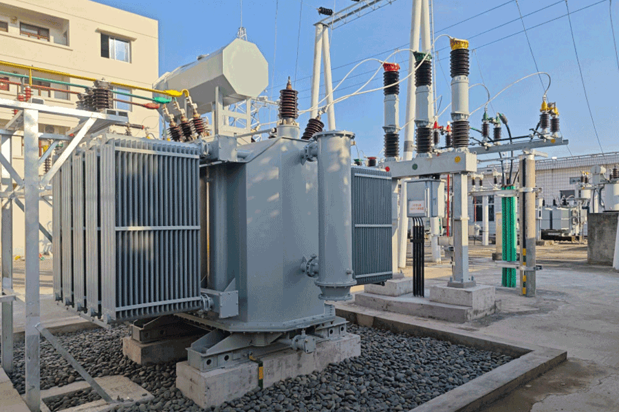






Choosing Transformer Copper Terminal Stud Specifications
Time:2026-09-16 17:59:04 Author:zhongbei Click:107
The transformer copper terminal stud is among the most overlooked components in transformer specification, yet it carries the full load current of the transformer and represents a critical interface between the transformer and the external electrical system. A poorly specified terminal stud creates a high-resistance connection that generates heat, accelerates oil oxidation, and eventually fails. An appropriately specified terminal stud provides decades of reliable service with routine inspection and maintenance. For B2B procurement engineers and transformer designers, understanding how to specify copper terminal studs that match the application requirements eliminates a common source of transformer reliability problems.
Material Selection and Copper Grades
The material grade of the copper terminal stud directly affects electrical performance, mechanical strength, and corrosion resistance. Not all copper grades are suitable for transformer terminal applications, and the distinction matters for long-term reliability.
Electrolytic tough pitch copper, designated ETP or C11000, is the most common material for transformer copper terminal studs. ETP copper offers electrical conductivity of 101 percent IACS combined with good mechanical workability and acceptable corrosion resistance. The small phosphorus content improves machining characteristics while maintaining conductivity. For most transformer applications, ETP copper provides the appropriate balance of electrical performance, mechanical strength, and cost.
Oxygen-free high conductivity copper, designated OFHC or C10100, offers marginally higher conductivity at 102 percent IACS and superior resistance to hydrogen embrittlement. OFHC copper is preferred for high-current applications where conductivity differences translate to significant losses, and for applications where the terminal stud may be exposed to hydrogen-rich environments. The premium cost of OFHC copper is justified only for applications with specific requirements that ETP copper cannot meet.
Silver-bearing copper, designated C11500 or C11600 with 0.03 to 0.12 percent silver content, provides improved resistance to annealing at elevated temperatures. Copper terminal studs in high-load or high-temperature applications benefit from silver-bearing grades because silver slows the recrystallization and softening that occurs when copper is held at elevated temperatures. The modest cost premium for silver-bearing copper provides improved performance for demanding applications.
Current Rating and Conductor Sizing
The current rating of the copper terminal stud must exceed the maximum continuous current the transformer will carry, with adequate thermal margin for overload conditions and abnormal operating temperatures.
Current density in the terminal stud determines the temperature rise at rated current. Standard practice limits current density to approximately 2 to 3 A per square millimeter for copper terminal studs in transformer applications. This density limit produces acceptable temperature rise at rated current while providing margin for overload conditions. Higher current density produces proportionally higher losses and temperature rise, accelerating connection deterioration.
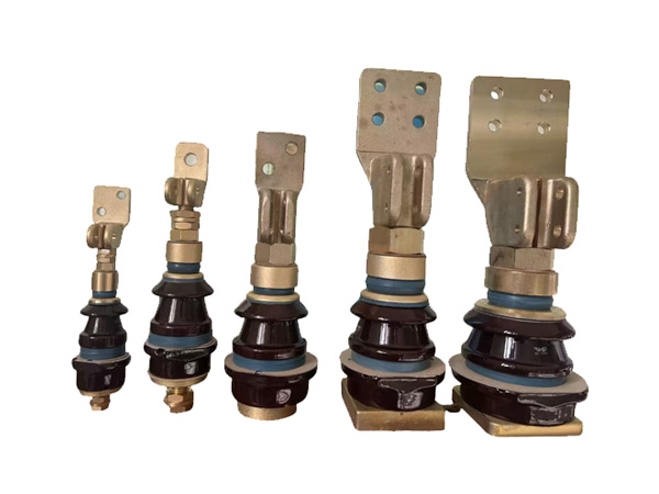
Calculate the required cross-sectional area by dividing the maximum continuous current by the selected current density. Round up to the next standard terminal stud size available from manufacturers. For a transformer with 2000 A maximum continuous current, the required area at 2.5 A/mm2 is 800 mm2, corresponding to a terminal stud diameter of approximately 32 mm. Common standard sizes—25 mm, 30 mm, 35 mm, 40 mm, 50 mm—provide appropriate options across the range of transformer ratings.
Consider short-circuit thermal withstand in addition to continuous current rating. A short-circuit current of 10 to 50 times normal current flows through the copper terminal stud for durations of 1 to 4 seconds during fault conditions. The terminal stud must withstand this short-circuit current without exceeding the temperature at which insulation materials degrade. Verify that the selected terminal stud size provides adequate short-circuit withstand per IEEE or IEC short-circuit calculation methods.
Thread Specification and Mechanical Interface
The threaded portion of the copper terminal stud serves both as a mechanical mounting element and as a current-carrying conductor. Thread specification affects both mechanical integrity and electrical performance.
Standard thread forms for transformer terminal studs include metric ISO threads, Unified National threads, and British Standard threads depending on the manufacturer and application region. Specify the thread standard and size appropriate for the application—metric M16, M20, M24, M30, M36, and M42 are common sizes for transformer copper terminal studs. The thread size must match the hardware used to secure busbar connections and any external equipment.
Thread quality and finish affect both mechanical reliability and electrical performance. Rolled threads provide better fatigue resistance than cut threads for applications subject to thermal cycling. Thread plating with silver or tin improves contact performance at the thread interface and reduces galling during assembly and disassembly. Specify thread plating consistent with the application requirements.
Mechanical strength requirements for the copper terminal stud thread depend on the forces imposed by busbar weight, conductor tension, and any short-circuit electromagnetic forces. The thread must resist yielding under maximum assembly torque and short-circuit loading without damage. Specify thread engagement length adequate for the loading conditions—typically a minimum of one thread diameter of engagement in properly designed hardware.
Terminal Head and Connection Interface Design
The terminal head—the portion of the copper terminal stud that interfaces with external connections—must accommodate the connection hardware while providing adequate contact area and current distribution.
Standard terminal head configurations include flat pad designs with drill-through holes for bolted busbar connections, threaded barrel designs for cable clamp connections, and combination designs with both pad and threaded sections. Select the configuration that matches the connection hardware used in the installation—bolted busbar connections require flat pad designs, cable clamp connections require threaded barrel designs.
Contact surface area at the terminal head must accommodate the connection hardware without excessive current density at the contact points. For bolted connections, the pad width must provide adequate clearance for bolt spacing and busbar routing. The hole pattern must match the busbar hardware—standard bolt circles of 38 mm, 50 mm, and 65 mm accommodate common busbar configurations.
Plating of the terminal head contact surfaces with silver or tin provides improved contact performance and corrosion resistance. Silver plating maintains low contact resistance throughout the service life better than unplated copper, particularly in environments with temperature cycling and humidity exposure. Specify silver plating of 0.003 to 0.005 mm thickness for contact surfaces subject to frequent assembly and disassembly.
Length and Mounting Configuration
The overall length of the copper terminal stud must accommodate the tank wall thickness, any insulation barriers, washers and hardware, and the connection hardware that will be installed externally. Insufficient length creates assembly problems; excessive length adds cost and may interfere with busbar routing.
Calculate the required length by summing the tank wall thickness, any bushings or insulating sleeves through the wall, the depth of threaded engagement in the internal hardware, and the external hardware stack-up including flat washers, spring washers, and the busbar or cable connection hardware. Specify length with adequate tolerance to accommodate manufacturing variations in tank thickness and hardware.
Mounting configuration in the transformer tank affects terminal stud specification. Studs mounted through tank flanges require sealing arrangements—typically conical seating or O-ring seals—that prevent oil leakage at the tank penetration. The sealing arrangement must be specified as part of the terminal stud specification, including the seal type, seal material, and the corresponding bore dimensions in the tank flange.
Environmental Considerations for Terminal Stud Selection
Environmental conditions at the installation site influence terminal stud specification beyond the basic electrical and mechanical requirements.
Corrosive environments accelerate terminal stud deterioration through oxidation and galvanic action. Coastal environments with salt spray, industrial environments with sulfur compounds, and outdoor installations subject to rain and pollution all require enhanced corrosion protection. Silver-plated copper terminal studs provide better corrosion resistance in these environments than unplated copper. For severely corrosive environments, specify nickel-plated terminals for the contact surfaces with silver plating on the threaded portion.
Temperature extremes affect both the terminal stud material performance and the connection hardware. Low temperatures increase brittleness and reduce impact resistance—verify that the selected copper grade maintains adequate toughness at the minimum expected ambient temperature. High temperatures reduce the allowable current rating—apply temperature derating factors when the terminal stud will operate in high ambient temperature environments.
Altitude affects cooling effectiveness and therefore current rating. Above 1000 meters elevation, the reduced air density decreases convective cooling, increasing temperature rise at a given current. Specify terminal studs with adequate current rating margin for the installation altitude, or select the next larger size to compensate for altitude-related cooling reduction.
Quality Verification and Inspection
Quality verification of received copper terminal studs confirms that the specified materials, dimensions, and finish have been delivered.
Material verification through mill test certificates confirms the copper grade and any alloying additions. Request material certifications from the supplier documenting the actual material used. For critical applications, confirm material identity through optical emission spectroscopy or similar analytical methods.
Dimensional inspection verifies that thread dimensions, overall length, head dimensions, and hole patterns match specifications. Use go/no-go gauges for thread inspection, calipers and micrometers for dimensional measurements. Document inspection results to support quality records.
Surface finish inspection confirms that plating thickness and coverage meet specifications. Use magnetic or eddy current thickness gauges to verify plating thickness at multiple points on the terminal head and threaded sections. Inspect for scratches, pits, or other surface defects that could affect performance.
Frequently Asked Questions
What is the difference between silver-plated and tin-plated copper terminal studs?
Silver plating provides superior contact performance and maintains low contact resistance throughout the service life, even at elevated temperatures. Silver does not oxidize significantly at normal operating temperatures. Tin plating is less expensive but oxidizes more readily, creating higher contact resistance over time. Specify silver plating for critical applications and for terminals that will experience elevated temperatures. Tin plating is acceptable for lower-current applications in clean indoor environments.
How do I determine the correct terminal stud size for a specific transformer rating?
Calculate the required cross-sectional area by dividing maximum continuous current by the selected current density—typically 2 to 3 A/mm2. Select the next standard terminal stud size above this calculation. Verify short-circuit withstand using the calculated fault current and duration. When in doubt between sizes, select the larger option—oversizing costs little while undersizing creates reliability problems.
Can copper terminal studs be repaired if threads are damaged?
Minor thread damage can sometimes be repaired with thread chasers or thread inserts. Severe thread damage requires replacement of the terminal stud. Thread inserts—helical coils that provide new threads within the damaged bore—restore the connection capability when the original threads cannot be cut to the original size. Evaluate repair economics against replacement cost for each situation.
What causes terminal stud connection failures?
Connection failures most commonly result from high contact resistance at the connection interface, which generates heat, accelerates oxidation, and creates a positive feedback loop of increasing resistance and temperature. Loose connections, surface contamination, improper torque, and galvanic corrosion at dissimilar metal interfaces all create high contact resistance. Proper installation procedures, appropriate surface preparation, and regular torque verification prevent connection failures.
How often should terminal stud connections be inspected and torqued?
Inspect and verify torque on copper terminal stud connections every 3 to 5 years during planned maintenance outages, or more frequently for transformers in harsh environments. Infrared thermography during peak load conditions identifies hot spots that indicate developing connection problems before they progress to failure. Thermal imaging surveys complement torque verification by detecting problems that torque alone might miss.
Conclusion
Selecting the correct copper terminal stud specification requires balancing material grade, current rating, mechanical requirements, and environmental considerations to match the application conditions. The investment in careful specification pays returns through decades of reliable service without the connection problems that plague undersized or improperly specified terminals. For B2B procurement engineers and transformer designers, the systematic approach outlined—selecting material grade based on conductivity and temperature requirements, sizing for current and short-circuit withstand, specifying thread and interface dimensions for mechanical integrity, and adding environmental protection where conditions require—produces terminal specifications that support transformer reliability throughout the equipment service life. The copper terminal stud may be a small component in the overall transformer specification, but its importance for electrical continuity and thermal management makes it worthy of the same careful attention given to major transformer components.
References
IEEE Std C57.12.90-2015, "Standard Test Code for Liquid-Immersed Distribution, Power, and Regulating Transformers," IEEE Power & Energy Society.
Holm, R., "Electric Contacts: Theory and Applications," Springer, 4th edition, 2010.
IEC 60865-1:2011, "Short-Circuit Currents – Calculation of Effects – Part 1: Definitions and Calculation Methods," International Electrotechnical Commission.
Kulkarni, S.V., and Khaparde, S.A., "Transformer Engineering: Design, Technology, and Diagnostics," CRC Press, 2012.
Pansini, A.J., "Power Transformer Fundamentals," Fairmont Press, 2018.
MORE
-
How DIN Standard Bushings Meet International Requirements
2026-09-16
-
Choosing Transformer Copper Terminal Stud Specifications
2026-09-16
-
How to Choose the Right Dry Type Transformer Capacity
2026-08-18
-
How to Source Reliable Transformer Parts Suppliers
2026-08-12
-
Pressure Relief Device Testing and Maintenance Guide
2026-08-12