





Dry Type Transformer Cooling Methods Explained
Time:2026-09-22 15:53:03 Author:zhongbei Click:120
Thermal management determines how much power a dry type transformer can deliver without exceeding safe operating temperatures. Unlike oil immersed transformers that rely on liquid circulation to move heat away from the core and windings, dry type transformers depend entirely on air movement—either natural convection or forced circulation—to dissipate the heat that winding resistance and core losses generate continuously during operation. Understanding how dry type transformer cooling methods work, which configuration suits which application, and what happens when cooling is inadequate, helps engineers, procurement specialists, and facility managers specify and operate transformers that deliver reliable performance throughout their expected service life.
Why Cooling Matters in Dry Type Transformers
A dry type transformer generates heat from two primary sources. Core losses in the magnetic circuit produce heat continuously whenever the transformer is energized, regardless of load. Winding losses—resistive heating in the conductors carrying load current—increase with the square of the load current. At full rated load, winding losses typically exceed core losses in distribution transformers, though the ratio varies with transformer design and loading profile.
This heat must be removed from the transformer windings to prevent insulation temperatures from exceeding the limits that determine service life. The insulation systems used in dry type transformers—typically Class F materials rated for 155 degrees Celsius or Class H materials rated for 180 degrees Celsius—degrade faster at elevated temperatures. A transformer operating consistently 10 degrees Celsius above its design temperature may lose half its expected insulation life. Effective dry type transformer cooling is not merely about capacity—it is fundamentally about preserving insulation integrity and extending equipment life.
The relationship between load and temperature rise is not linear. At low loads, temperature rise is minimal. As load increases, temperature rise grows roughly with the square of the current. A transformer loaded at 80 percent of rated capacity may experience only 64 percent of the full-load temperature rise, leaving some thermal margin. A transformer loaded at 110 percent of rated capacity generates 121 percent of full-load losses, potentially exceeding design temperature limits and beginning the thermal aging process that progressively degrades insulation.

Natural Air Cooling (AN): Self-Cooling Principles
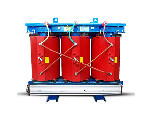
Natural air cooling—designated AN in IEC nomenclature—relies on the buoyant rise of heated air to create circulation without any mechanical assistance. When transformer windings heat up, the surrounding air warms, becomes less dense, and rises upward, drawing cooler air from below to replace it. This self-sustaining circulation pattern carries heat away from the windings and dissipates it through the transformer enclosure and surrounding environment.
The cooling effectiveness of AN configuration depends on several factors that engineers must consider during specification. The temperature difference between the windings and ambient air drives natural convection—the larger the difference, the stronger the circulation and the more heat removed. Enclosure design influences air flow paths, with properly designed ventilation openings allowing uninhibited circulation while preventing foreign object ingress. Installation location matters—enclosed spaces with restricted air movement significantly reduce AN cooling effectiveness compared to open installations in well-ventilated rooms.
AN-cooled dry type transformers offer practical advantages that make them the preferred choice for many applications. The absence of fans eliminates moving parts that could fail, reducing maintenance requirements and improving reliability. The absence of fan noise makes AN-cooled transformers suitable for noise-sensitive environments such as offices, hospitals, and commercial buildings. The absence of fan power consumption improves transformer efficiency, particularly at light loads where fan power represents a larger fraction of total losses.
However, AN cooling imposes a fundamental limitation on transformer capacity. The heat transfer rate achievable through natural convection is physically limited by the thermodynamic properties of air. Beyond a certain winding temperature, natural convection cannot remove heat fast enough to prevent temperature from rising further. This thermal ceiling means that AN-cooled transformers are typically limited to ratings below approximately 2500 kVA at standard voltage classes, though the specific limit varies with voltage class, enclosure design, and installation conditions.
Forced Air Cooling (AF): Enhanced Heat Removal
Forced air cooling—designated AF—uses fans or blowers to drive air across the transformer windings at velocities significantly higher than natural convection alone can achieve. By pushing air through the windings rather than relying on buoyancy-driven circulation, AF configuration increases the rate of convective heat transfer and enables the transformer to dissipate more losses at the same temperature rise.
The practical effect of AF cooling is typically a 25 to 50 percent increase in transformer capacity compared to the same unit operating in AN mode. A 1000 kVA AN-rated transformer might achieve 1250 to 1500 kVA when equipped with AF cooling fans operating at rated voltage and frequency. This capacity increase allows AF-cooled transformers to handle peak loads or temporary overloads that would exceed AN thermal limits.
Fan placement and air flow design significantly influence AF cooling effectiveness. Cross-flow configurations draw air horizontally through the winding assembly, while axial configurations push air vertically along the winding length. Some designs use fans on multiple faces to ensure even air distribution across all winding surfaces. The goal is uniform cooling—hot spots that develop in poorly ventilated areas become the limiting factor for transformer capacity even when average temperatures appear acceptable.
AF cooling introduces several considerations that affect specification decisions. Fan power consumption reduces overall efficiency, particularly at light loads when the fans may run continuously but the transformer carries little current. Fan noise increases with fan speed and may be significant in noise-sensitive environments. Fan reliability becomes a maintenance consideration—fans operate continuously during transformer service, and fan failures can lead to thermal overload if not detected promptly. Some AF designs incorporate variable-speed fans or staged fan operation to address noise and efficiency concerns at reduced loads.
Thermal Monitoring and Temperature Rise Ratings
Understanding temperature rise ratings requires clarity about what these specifications mean and how they relate to actual operating conditions. When a transformer is rated for a particular temperature rise—say 80 degrees Celsius or 100 degrees Celsius—this value represents the average temperature increase of the windings above the surrounding ambient air temperature at rated load under standard test conditions.
The standard test conditions assume a maximum ambient temperature of 30 degrees Celsius for Class F insulation and 40 degrees Celsius for Class H insulation. At these ambient temperatures, the rated temperature rise applies at rated load. At higher ambient temperatures—as occur in hot climate installations, inadequately ventilated electrical rooms, or outdoor enclosures in summer—the transformer reaches the same winding temperature at lower load levels. This relationship means that transformers specified for moderate climates may require derating when installed in hot environments.
Modern dry type transformers typically incorporate embedded temperature sensors in the windings that provide direct measurement of hot spot temperatures—the hottest points in the winding assembly that determine insulation stress. These sensors feed monitoring systems that can trigger alarms when temperatures exceed safe limits or initiate load reduction when temperatures approach design limits. Temperature monitoring transforms the thermal constraints imposed by dry type transformer cooling methods from abstract specifications into operational information that enables safe load management.
The thermal time constant of a dry type transformer—typically 2 to 6 hours depending on size and design—determines how quickly winding temperatures respond to load changes. Short-duration overloads may not fully heat the windings before the load returns to normal levels, allowing temporary overloads beyond the continuous rating without reaching thermal equilibrium. Understanding the thermal time constant helps operators manage load profiles that include short-duration peaks without unnecessarily restricting operations.
Thermal Management in Enclosed and Restricted Installations
The cooling effectiveness of any dry type transformer cooling method depends critically on the installation environment. A transformer specified correctly for an open installation may experience severe thermal problems when installed in an enclosure that restricts air flow.
Enclosure design must account for heat rejection from the transformer. The total heat output in kilowatts equals the transformer losses at the operating load level. This heat must be removed from the enclosure without allowing internal temperatures to exceed transformer design limits. Simple calculations determine ventilation requirements—each kilowatt of heat output requires approximately 100 cubic meters per hour of air flow at a 20 degree Celsius temperature rise across the enclosure. When natural ventilation is insufficient, mechanical ventilation or enclosure air conditioning becomes necessary.
Clearance requirements around transformers ensure adequate air flow for cooling. Minimum clearances between transformer surfaces and enclosure walls or other equipment are specified by the manufacturer and by safety standards such as IEC and NEC. These clearances are not arbitrary—they provide the air flow passages necessary for effective cooling. Reducing clearances to save space risks thermal performance degradation that offsets the space savings.
For transformers installed in multi-unit substations or adjacent to other heat-generating equipment, thermal interaction effects may reduce cooling effectiveness below what individual transformer specifications predict. Engineering studies of substation thermal environment help identify such interactions and guide installation arrangements that prevent thermal interference.
Selecting the Right Cooling Method for Your Application
The choice between AN and AF cooling depends on the specific requirements of the application, considering load profile, ambient conditions, environment, noise constraints, and maintenance capability.
For applications with relatively stable loads below the AN rating, where the transformer operates continuously near its rated capacity, AN cooling provides adequate thermal management with minimal maintenance burden. Commercial buildings, office parks, and industrial facilities with predictable load profiles often suit AN-cooled transformers. The absence of fans simplifies maintenance and eliminates fan-related failure modes.
For applications with variable loads that include periods exceeding AN thermal limits, AF cooling provides the additional capacity needed during peak demand periods. Heavy industrial facilities with shift-based operations, manufacturing plants with periodic high-power processes, and data centers with variable computing loads benefit from the overload capacity that AF cooling provides. The ability to operate above AN rating during peak periods without thermal overload enables more efficient transformer sizing.
Noise-sensitive applications favor AN cooling where load requirements permit. The hum and vibration of transformer cores represent the primary noise sources, but fan noise in AF-cooled transformers adds a continuous background noise that may be unacceptable in offices, hospitals, or residential areas. When AF cooling is necessary for capacity reasons but noise is a concern, specify low-speed fans, variable-speed fans with reduced-speed modes, or sound-attenuated enclosures to minimize fan noise contribution.
For critical facilities where cooling system failure could cause thermal overload, consider redundancy provisions in AF designs. Duplicate fan systems with independent power supplies ensure that single fan failures do not eliminate forced cooling capability. Temperature monitoring with alarm functions provides early warning when cooling effectiveness degrades, enabling load reduction or fan replacement before thermal overload occurs.
Maintenance Practices for Optimal Cooling Performance
Maintaining cooling effectiveness throughout transformer service life requires attention to the factors that influence heat transfer: air flow passages, cooling surfaces, and fan operation.
Dust accumulation on transformer windings and cooling surfaces progressively reduces heat transfer efficiency. In industrial environments with airborne particulates, regular cleaning—typically annual or biennial depending on contamination levels—restores cooling effectiveness. The cleaning procedure must avoid damaging winding insulation or contaminating the internal surfaces; manufacturer guidance specifies acceptable cleaning methods and materials.
AF cooling fan maintenance includes regular inspection of fan motors, blades, and bearings for signs of wear or deterioration. Fan vibration monitors can detect bearing degradation before complete fan failure. Replace fan components showing wear before they fail, ideally during planned maintenance outages rather than as emergency response to fan problems.
Ventilation passages in transformer enclosures require inspection and cleaning to ensure that air flow paths remain unobstructed. Accumulated dust, debris, or foreign objects can block critical flow passages, creating hot spots that reduce effective transformer capacity. Include enclosure ventilation in regular maintenance inspection checklists.
Frequently Asked Questions
What is the difference between AN and AF cooling designations?
AN designates natural air cooling, where heat dissipation occurs through natural convection without mechanical assistance. AF designates forced air cooling, where fans or blowers actively circulate air to enhance heat removal. AN-cooled transformers are self-cooled; AF-cooled transformers use fans to achieve higher capacity ratings than natural convection alone can support.
Can an AN-cooled transformer handle temporary overloads?
Yes, within limits determined by the thermal time constant and the magnitude of the overload. Short-duration overloads may be accommodated because the thermal time constant prevents winding temperatures from reaching equilibrium during the brief overload period. However, sustained overloads approaching or exceeding the AN rating will cause temperatures to rise above design limits, accelerating insulation aging. Temperature monitoring enables operators to manage overloads within safe thermal limits.
How does installation altitude affect dry type transformer cooling?
Above approximately 1000 meters elevation, reduced air density decreases convective cooling effectiveness. Standard derating factors—typically 0.3 to 0.4 percent per 100 meters above 1000 meters—reduce the effective transformer rating. Specify transformers with altitude derating or select larger ratings to compensate when installing at significant elevations.
What temperature rise rating should I specify for my application?
Temperature rise ratings typically range from 80 degrees Celsius to 150 degrees Celsius for dry type transformers. Lower temperature rise designs are more efficient and operate at lower temperatures, extending insulation life, but are larger and more expensive for equivalent kVA ratings. Higher temperature rise designs are smaller and less expensive but operate closer to insulation temperature limits. Balance first cost against efficiency and longevity requirements for your specific application.
How often should dry type transformer cooling systems be inspected?
Inspect cooling effectiveness during routine transformer inspections—typically monthly to quarterly depending on facility procedures. Annual thermal imaging during peak load conditions identifies any developing hot spots. AF fan maintenance should follow manufacturer recommendations, typically including annual inspection and bearing replacement at defined intervals. Keep ventilation passages clear and verify that air flow is not obstructed by accumulated dust or foreign materials.
Conclusion
Dry type transformer cooling methods determine not only how much power a transformer can deliver but also how long it will last and how reliably it will perform throughout its service life. AN cooling provides simple, maintenance-free operation for applications within its thermal capacity, while AF cooling extends capacity for demanding load profiles at the cost of increased complexity and maintenance requirements. Selecting the appropriate cooling configuration requires understanding the interaction between load profile, ambient conditions, installation environment, and the thermal characteristics of each cooling method. Engineers and procurement specialists who match cooling configuration to application requirements ensure that their transformer investments deliver reliable performance without premature aging or unexpected thermal limitations. As facilities evolve and load profiles change, the flexibility of AF cooling configurations—capable of handling peak demands that AN-only designs cannot accommodate—often proves valuable in supporting operational flexibility while maintaining the safety and reliability that industrial power distribution demands.
References
IEC 60076-11:2018, "Power Transformers – Part 11: Dry-Type Transformers," International Electrotechnical Commission.
IEEE Std C57.12.01-2020, "General Requirements for Dry-Type Distribution and Power Transformers," IEEE Power & Energy Society.
Kulkarni, S.V., and Khaparde, S.A., "Transformer Engineering: Design, Technology, and Diagnostics," CRC Press, 2012.
Pansini, A.J., "Power Transformer Fundamentals," Fairmont Press, 2018.
MORE
-
Dry Type Transformer Cooling Methods Explained
2026-09-22
-
Selecting the Right Pressure Relief Device for Transformers
2026-09-16
-
Mechanical vs Magnetic Oil Level Indicators for Transformers
2026-09-16
-
How DIN Standard Bushings Meet International Requirements
2026-09-16
-
Choosing Transformer Copper Terminal Stud Specifications
2026-09-16