





Mechanical vs Magnetic Oil Level Indicators for Transformers
Time:2026-09-16 18:03:51 Author:zhongbei Click:129
Monitoring oil level in a transformer conservator tank seems straightforward—oil level should be visible, and low oil should trigger an alarm. Yet the choice between mechanical and magnetic oil level indicators involves trade-offs in reliability, maintenance requirements, environmental robustness, and cost that affect transformer fleet management across the equipment service life. Maintenance engineers and utility specifiers who understand these trade-offs can select indicators that reduce false alarms, simplify maintenance, and provide accurate oil level information under the specific conditions their transformers face. This article examines both indicator types systematically to support informed selection decisions.
Conservator Tank Oil Level Monitoring Fundamentals
Before comparing indicator types, understanding why oil level monitoring matters clarifies the selection criteria. The conservator tank on an oil-filled transformer provides expansion space for oil as temperature increases during operation. As oil volume changes with temperature, the oil level in the conservator rises and falls—typically 10 to 15 percent of tank volume across the normal operating temperature range.
Oil level monitoring serves two purposes. First, it detects abnormal oil loss from leaks or internal faults. Second, it confirms adequate oil volume for insulation during all operating conditions. A conservator running persistently low on oil may indicate an undetected leak that will eventually cause dielectric failure, or internal fault conditions that are consuming oil through arcing or thermal decomposition. Either condition requires investigation before catastrophic failure occurs.
The oil level indicator must therefore provide accurate reading across the operating temperature range while remaining reliable in the harsh conditions present at transformer installations—temperature extremes, vibration, moisture, and occasional physical contact during maintenance activities. Both mechanical and magnetic indicator designs address these requirements differently.
Mechanical Float-Type Oil Level Indicators
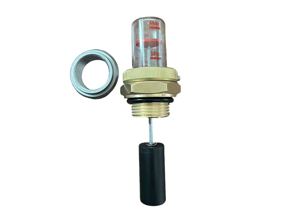
Mechanical float indicators use a buoyant float that rises and falls with oil level, transmitting the position through a rod linkage to a dial gauge visible through a window in the conservator tank. This straightforward mechanical principle has served transformer applications for decades and remains widely deployed in aging transformer fleets.
The float mechanism responds directly to oil buoyancy, providing immediate indication of level changes. The linkage design transmits float position to the gauge without electronic components, eliminating power supply requirements and reducing failure modes. In low-voltage indicator circuits, the float position can actuate alarm contacts through simple mechanical switching.
However, mechanical indicators face limitations in demanding environments. The rod linkage contains multiple pivot points where corrosion, debris accumulation, or binding can cause indication errors. Float linkage mechanisms have been known to seize partially, causing the indicator to read correctly at one temperature but stick at others. Rod linkage seals at the tank penetration represent potential leak paths—mechanical indicators with rod penetrations require maintenance attention to these seals throughout the service life.
Physical damage during maintenance creates additional failure modes. Workers accessing the transformer conservator can inadvertently bend float rods or dislodge floats from their linkages. The indicator may appear functional while actually providing inaccurate readings—a dangerous condition if reliance is placed on the indicated level.
Magnetic Coupling Oil Level Indicators
Magnetic indicators address the reliability limitations of rod linkage designs by using magnetic coupling to transmit float position through the tank wall without mechanical penetration. A float inside the tank carries a magnet that interacts with magnetically-coupled indicator elements on the tank exterior, moving a follow pointer or dial without any physical connection through the tank wall.
The absence of tank wall penetration is the defining advantage of magnetic indicators. Without penetrations, there are no seal points that could leak. Without linkage mechanisms, there are no pivot points that could bind. The magnetic coupling operates through the tank wall, typically constructed of non-magnetic material, providing reliable indication without introducing leak paths or mechanical complexity.
Magnetic indicators also provide better resistance to the vibration and mechanical stress present in transformer environments. The magnetic coupling tolerates moderate tank movement and vibration without losing indication accuracy. This robustness makes magnetic indicators particularly suitable for transformers in high-vibration applications or those subject to seismic loading.
The primary limitation of magnetic indicators involves the indirect coupling principle. Magnetic force transmission requires precise alignment of magnetic elements, and the relationship between float position and indicator reading depends on the magnetic interaction geometry. Some magnetic indicator designs exhibit non-linear response across the operating range, with indication accuracy varying at different level positions. High-quality magnetic indicators address this through optimized magnetic geometry that provides linear response across most of the operating range.
Accuracy and Temperature Compensation Considerations
Oil level accuracy requirements depend on the application and the consequences of incorrect indication. For most distribution transformers, indication accuracy within 5 to 10 percent of tank volume is adequate to detect significant oil loss. For critical transformers where precise monitoring supports condition-based maintenance, tighter accuracy requirements may justify more sophisticated indicator designs.
Both indicator types face temperature-related accuracy challenges. Oil density changes with temperature, affecting float buoyancy and the position at which the float settles for a given oil volume. At higher temperatures, oil density decreases and the float sits lower for the same oil volume. At lower temperatures, higher oil density causes the float to sit higher. This temperature effect is most pronounced in mechanical float indicators where the float responds directly to buoyancy changes.
Temperature compensation in oil level indicators addresses this effect by providing reference marks at defined temperatures—typically marked at reference temperatures of 20 degrees Celsius or ambient temperature conditions. Using these marks to calibrate readings at known temperatures improves accuracy. Some modern digital indicators incorporate temperature sensors and automatic compensation algorithms that correct level readings based on oil temperature.
Alarm Contact Integration and Remote Monitoring
Beyond local visual indication, oil level indicators often integrate with alarm systems that alert operators to low oil conditions. The contact integration approach differs significantly between indicator types.
Mechanical float indicators typically actuate alarm contacts through mechanical switching triggered by the float position. A low-level alarm activates when the float drops below a defined position, closing a contact in the alarm circuit. These mechanical contact systems are reliable but require periodic contact cleaning and adjustment to maintain proper actuation points.
Magnetic indicators can integrate contacts through several approaches. Some magnetic indicators include integral contacts that actuate based on magnetic position. Others drive electronic sensors through the tank wall without physical penetration, providing contact outputs without mechanical switching. Electronic contact integration offers advantages in long-term stability and the ability to provide multiple alarm levels—warning at moderately low oil and critical alarm at severely low oil.
For remote monitoring applications, both indicator types can drive SCADA-compatible outputs. Mechanical indicators may require addition of electronic position sensors. Magnetic indicators with electronic integration provide direct communication outputs that integrate with modern monitoring systems without additional hardware.
Installation and Maintenance Requirements
Installation complexity differs significantly between indicator types. Mechanical float indicators require tank penetration for the rod linkage, creating installation steps that must be performed during transformer assembly or during major maintenance when the tank can be opened. Once installed, mechanical indicators require periodic inspection of linkage freedom and seal integrity.
Magnetic indicators install through a single flange connection without tank penetration. This simplifies installation and eliminates the leak path associated with rod penetrations. The magnetic coupling does not require adjustment after installation, reducing commissioning complexity.
Maintenance requirements continue to differ throughout service life. Mechanical indicators require periodic linkage inspection, cleaning, and adjustment to ensure free movement. Seal inspection and replacement prevents oil leakage through the rod penetration. Float integrity should be verified periodically, particularly for indicators that have operated in harsh environments where float damage may have occurred.
Magnetic indicators require minimal maintenance beyond periodic cleaning of the external indicator window and verification of magnetic coupling integrity. The absence of mechanical linkages eliminates the primary failure modes of mechanical indicators. External cleaning maintains visibility of the indicator scale, which is the main maintenance activity for properly functioning magnetic indicators.
Selection Guidance for Different Applications
The choice between mechanical and magnetic indicators depends on factors specific to each transformer application and maintenance environment.
For new transformer procurement, magnetic indicators represent the current technology preference for most applications. The reliability advantages, simplified installation, and reduced maintenance burden justify the typically higher first cost. Specify magnetic indicators for transformers in harsh environments, for transformers in seismic areas where mechanical linkages face additional stress, and for transformers where maintenance access is difficult.
For existing transformers with mechanical indicators, evaluation of replacement versus retention depends on indicator condition and maintenance history. Indicators showing evidence of linkage binding, seal leakage, or repeated false alarms warrant replacement with magnetic indicators. Retain well-functioning mechanical indicators in transformers with otherwise limited remaining service life where the cost of replacement cannot be justified.
Frequently Asked Questions
Can magnetic oil level indicators be retrofitted to transformers with mechanical indicators?
Yes, magnetic indicators can replace mechanical indicators in most transformer designs. The retrofit involves removing the mechanical indicator assembly including the rod penetration, and installing a magnetic indicator on a compatible tank connection. Tank modification may be required if the original mechanical penetration flange is not compatible with magnetic indicator mounting. Consult the magnetic indicator manufacturer for specific retrofit guidance.
What causes false low oil level alarms in transformer indicators?
False alarms in mechanical indicators typically result from linkage binding, float positioning problems, or contact adjustment errors. Temperature-related buoyancy changes can also trigger false alarms if alarm set points are not appropriately positioned within the operating range. In magnetic indicators, false alarms may result from electronic sensor problems or improper alarm set point configuration.
How do I verify that an oil level indicator is reading accurately?
Verification requires comparing indicated level against actual oil volume in the conservator at known temperature conditions. Drain the transformer to a measured level and compare against the indicator reading at the same temperature. Repeat at multiple level positions to verify linear response. Any significant deviation indicates indicator problems requiring investigation and correction.
Do both indicator types work with all transformer oil types?
Both mechanical and magnetic indicators work with mineral oil, ester oil, and silicone oil. However, buoyancy differs between oil types due to density differences—esters and silicones have lower density than mineral oil. Float selection must match the oil type in service. Verify that the indicator float is rated for the specific oil type in the transformer.
What is the expected service life of oil level indicators?
Well-maintained mechanical float indicators commonly operate for 20 to 25 years before requiring major maintenance or replacement. Magnetic indicators typically achieve 25 to 30 years of reliable service with minimal maintenance. The longer service life of magnetic indicators contributes to lower lifecycle cost despite higher first cost.
Conclusion
The comparison between mechanical and magnetic oil level indicators reveals clear technology advantages for most transformer applications. Magnetic indicators provide superior reliability, simplified installation, and reduced maintenance burden through their tank wall magnetic coupling principle. Mechanical float indicators remain viable for applications where their characteristics are appropriate, and many mechanical indicators continue reliable service in well-maintained transformer fleets. For new transformer specifications and retrofit decisions, the selection criteria outlined—application environment, maintenance capability, alarm integration requirements, and lifecycle cost considerations—enable decisions that match indicator technology to specific requirements. Investing in appropriate oil level monitoring technology supports the broader transformer reliability objectives that depend on accurate, timely detection of abnormal oil loss before that loss progresses to dielectric failure.
References
IEEE Std C57.12.00-2015, "Standard for General Requirements for Liquid-Immersed Distribution, Power, and Regulating Transformers," IEEE Power & Energy Society.
IEC 60247:2004, "Insulating Liquids – Measurement of Relative Permittivity, Dielectric Dissipation Factor and DC Resistivity," International Electrotechnical Commission.
Kulkarni, S.V., and Khaparde, S.A., "Transformer Engineering: Design, Technology, and Diagnostics," CRC Press, 2012.
CIGRE Working Group A2.37, "Transformer Reliability Survey," Technical Brochure 542, 2015.
IEEE Std C57.106-2015, "Guide for Acceptance and Maintenance of Insulating Oil in Equipment," IEEE Power & Energy Society.
MORE
-
Dry Type Transformer Cooling Methods Explained
2026-09-22
-
Selecting the Right Pressure Relief Device for Transformers
2026-09-16
-
Mechanical vs Magnetic Oil Level Indicators for Transformers
2026-09-16
-
How DIN Standard Bushings Meet International Requirements
2026-09-16
-
Choosing Transformer Copper Terminal Stud Specifications
2026-09-16