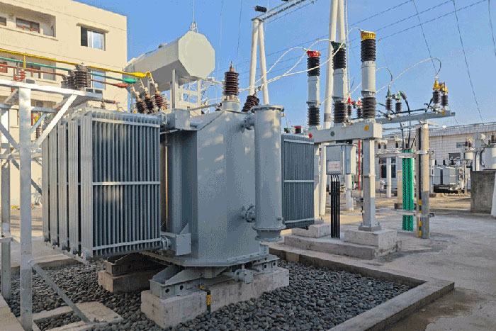
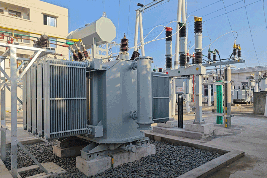






Oil Level Indicator for Transformer: What Does an Oil Level Indicator Do in a Transformer?
Time:2026-06-24 18:44:41 Author:zhongbei Click:132
Among the many auxiliary components that ensure transformer reliability, the oil level indicator plays a quiet but critical role. It is the first line of detection when an oil level indicator problem develops—before dissolved gas anomalies, before winding temperature spikes, before catastrophic failure. For B2B maintenance teams and procurement engineers, understanding this component's function, failure modes, and specification criteria is essential for asset management programs targeting zero unplanned transformer downtime.
The Role of an Oil Level Indicator in Transformer Design
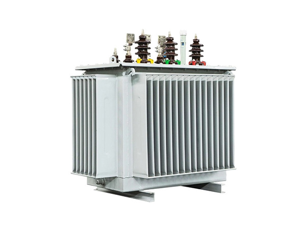
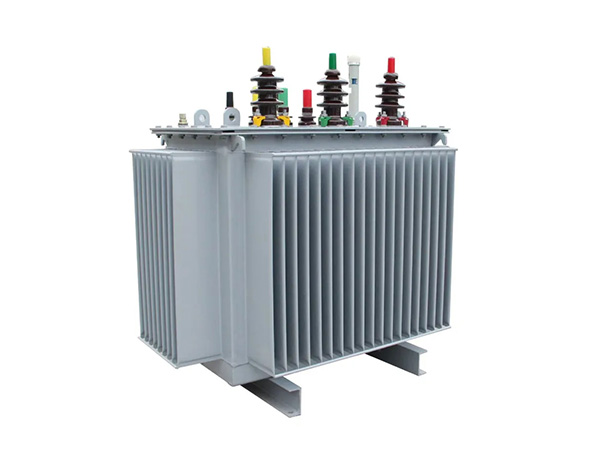
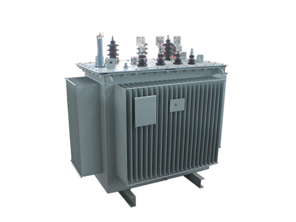
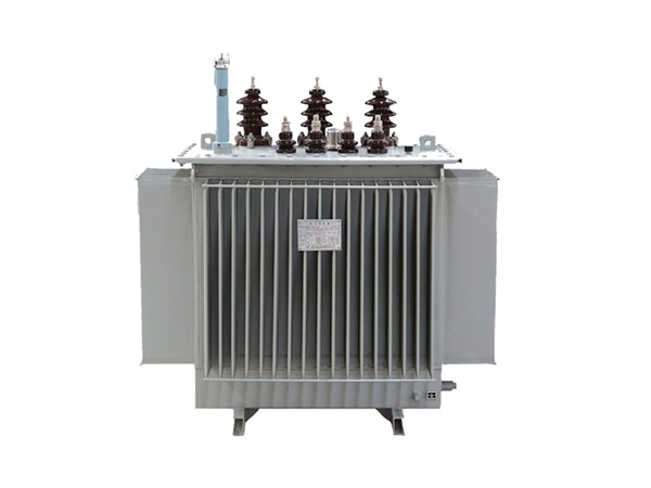
A transformer oil level indicator measures and displays the oil level within the conservator tank relative to a calibrated scale. The conservator tank is a cylindrical vessel mounted above the main oil immersed transformer tank, connected by a short pipe. As oil temperature rises under load, it expands; as it cools, it contracts. The conservator accommodates this volume change—typically 5–8% of total oil volume for distribution transformers—while maintaining a positive head pressure on the main tank seals.
The oil level indicator continuously displays whether the conservator oil level is within the acceptable range marked on the dial or scale. This visual or remote signal provides immediate confirmation of oil inventory integrity. Since oil is the primary insulation and cooling medium, any unexplained loss of oil directly compromises transformer safety and remaining life.
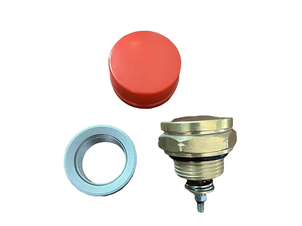
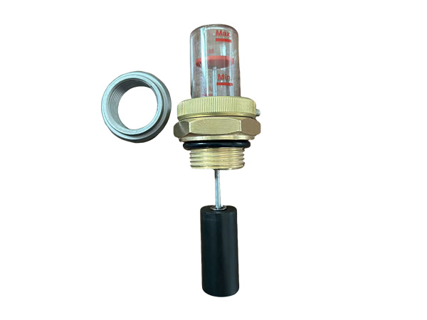
How Oil Level Indicators Work
Modern oil level indicator designs fall into three principal types:
Magnetic float type: A float inside the conservator rises and falls with oil level. A magnet on the float drives an indicating needle on the external dial. This is the most common design, offering reliability without requiring power supply. The magnetic coupling eliminates the need for mechanical penetrations through the tank wall.
Float-type direct reading: A mechanical float with an extending rod provides direct visual reading through a sight glass window. Simpler construction but less suited for remote monitoring and outdoor exposure.
Capacitance or ultrasonic type: Electronic sensors measure oil level by capacitance changes or ultrasonic reflection. These support digital output (4–20 mA, Modbus) for integration with SCADA and transformer monitoring systems. Higher cost but enables condition-based maintenance programs.
Each design serves a different monitoring depth: basic dial indicators for visual inspection rounds, and electronic sensors for integrated asset management systems on critical transformers.
Why Oil Level Monitoring Is Critical
Oil loss in an oil immersed transformer progresses through predictable stages:
Minor leak: Slow seepage through degraded gaskets or seal failure. Oil level drops gradually over weeks or months. The oil level indicator shows a declining trend on periodic inspection.
Accelerated loss: If leak rate exceeds oil expansion compensation, the level falls below the minimum mark. At this point, the transformer should be de-energized for investigation. Continuing operation with low oil risks partial discharge initiation at exposed winding sections.
Catastrophic failure: Complete oil loss leads to rapid insulation breakdown, internal arcing, and tank rupture. Repair costs vastly exceed leak investigation and repair.
Industry experience from CIGRE Working Group A2.37 confirms that oil-related failures account for approximately 30% of all transformer failures, with leaks representing the majority of oil-related events. The oil level indicator is the most accessible early warning device for this failure category.
Common Failure Modes of Oil Level Indicators
Like any mechanical or electronic device, the oil level indicator itself can fail. Maintenance teams should be aware of these common failure modes:
Float damage or sinking: In oil-filled conservators, the float can lose buoyancy due to oil ingress through a crack in the float shell. A sunken float reads permanently low or zero regardless of actual oil level. Annual oil sampling provides an opportunity to verify float integrity.
Magnetic coupling degradation: Over years of thermal cycling, the magnetic coupling between float magnet and indicator needle can weaken, causing sluggish response or reading inaccuracy. Calibration verification against known oil volume is recommended during major outages.
Glass or dial damage: Physical impact, UV degradation, or thermal cycling can crack the protective window, allowing moisture ingress and condensation on the dial face. This produces false low readings.
Electronic sensor drift: For capacitance or ultrasonic sensors, electronics drift over time. Regular calibration against physical oil volume measurement corrects drift before it produces false alarms or missed events.
Sticking or binding: The float arm mechanism can bind against conservator wall deposits or corrosion products, freezing the indicator at a fixed position.
Installation and Commissioning Considerations
Proper oil level indicator installation ensures reliable long-term performance:
Mount the indicator at a position providing clear visibility during routine inspection walks—typically at eye level on the conservator side or front panel.
For outdoor transformers, specify indicators with UV-stabilized polycarbonate windows and corrosion-resistant housings rated to IP65 or higher.
During commissioning, record the indicator reading against measured oil volume and top-oil temperature. This establishes a calibrated baseline for future trend analysis.
For transformers with online monitoring systems, specify indicators with 4–20 mA output for integration. Confirm signal range corresponds to minimum and maximum calibrated positions.
Include the indicator in the transformer nameplate documentation and maintenance log schema. Trend data over time is more valuable than a single reading.
Maintenance Best Practices
An effective oil level indicator maintenance program requires both inspection and periodic verification:
Daily or weekly inspection rounds: Record indicator reading alongside ambient temperature and transformer load. A sustained declining trend—not a single reading—is the reliable indicator of a developing leak.
Monthly visual inspection: Check for physical damage, condensation under the window, and evidence of oil seepage around the indicator housing.
Annual float verification: During planned outages, verify float buoyancy by observing indicator response to known volume changes. An out-of-tolerance reading triggers recalibration or replacement.
Replacement intervals: On transformers older than 15 years, budget for oil level indicator replacement as part of major refurbishment, regardless of observed condition. Aging floats and magnetic couplings are reliability liabilities approaching end of life.
Selecting the Right Oil Level Indicator
Specification should match the transformer's criticality and monitoring infrastructure:
Standard distribution transformers: Magnetic float dial indicator with minimum/maximum marks, IP54 enclosure, -30°C to +55°C operating range.
Critical or remote transformers: Electronic capacitance sensor with 4–20 mA output, compatible with existing SCADA RTU input. Alarm set points configurable for low-level warning and critical-low trip.
Generator step-up transformers: Dual-sensor configuration with both local dial and remote electronic output. Redundant monitoring justifies higher component cost on high-value units.
Retrofit applications: Retrofit kits are available for most common indicator sizes. Verify compatibility with existing conservator connection and confirm threading and sealing specifications before ordering.
Frequently Asked Questions
What oil level is considered normal on a transformer?
The acceptable oil level range is marked on the oil level indicator dial—typically between the minimum and maximum marks. The correct level varies with oil temperature; the indicator scale accounts for thermal expansion, showing the correct level at a reference temperature (commonly 20°C). Always interpret readings in context of transformer temperature and loading history.
Can an oil level indicator give false readings?
Yes. Float sinking, magnetic coupling degradation, or condensation on the dial can produce inaccurate readings. Monthly visual inspection and annual float verification detect most failure modes. Treat sudden unexpected readings—a sharp drop or rise without corresponding temperature change—as an investigation trigger, not a confirmed oil level event.
How does cold weather affect oil level readings?
At low temperatures, oil contracts and the oil level indicator reading drops. This is normal behavior. A reading at -10°C that is within the normal band at that temperature does not indicate a leak. The critical check is trend: if the reading is lower than expected for the current temperature, investigate further.
What should I do if the indicator shows critically low oil?
Immediately notify the asset owner and initiate the transformer emergency response procedure. Depending on transformer rating and load, this may require immediate de-energization. Do not continue operating a transformer with confirmed critically low oil—it poses an immediate fire and failure risk.
Conclusion
The oil level indicator is a deceptively simple component that provides irreplaceable asset health information. Its value lies not in complexity but in continuous availability—every inspection walk, every operator round, every thermography survey benefits from the oil level confirmation it provides. For B2B maintenance teams, treating this indicator as a genuine monitoring device rather than a passive gauge is the first step toward proactive oil loss detection. Specification should match the transformer's criticality, with electronic sensors justified on high-value assets where early warning enables condition-based intervention. A well-maintained oil level indicator, read and logged systematically, consistently proves its worth by catching oil leaks before they progress to forced outages.
References
CIGRE Working Group A2.37, "Transformer Reliability Survey," Technical Brochure 542, 2015.
IEEE Std C57.106-2015, "Guide for Acceptance and Maintenance of Insulating Oil in Equipment," IEEE Power & Energy Society.
IEC 60247:2004, "Insulating Liquids – Measurement of Relative Permittivity, Dielectric Dissipation Factor (tan δ) and d.c. Resistivity," International Electrotechnical Commission.
Kulkarni, S.V., & Khaparde, S.A., "Transformer Engineering: Design, Technology, and Diagnostics," CRC Press, 2012.
MORE
-
Transformer Components Most Likely to Require Replacement
2026-07-24
-
Signs Your Transformer Oil Level Indicator Needs Replacement
2026-07-11
-
dry-type-transformers-for-commercial-buildings
2026-07-11
-
DIN Standard Porcelain Bushings: Features and Benefits
2026-07-11
-
Copper vs Aluminum Terminal Studs for Transformers
2026-07-11