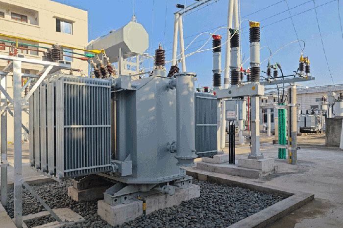
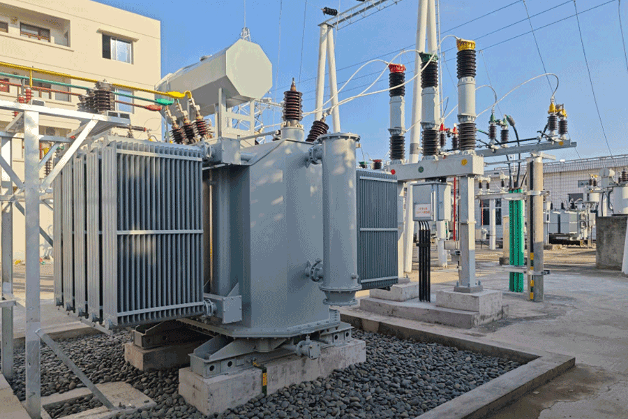






Transformer Components Most Likely to Require Replacement
Time:2026-07-24 15:23:11 Author:zhongbei Click:136
Every transformer asset manager eventually faces the same question: which transformer parts will need replacement before end of life, and when? The answer determines maintenance budgets, outage planning, and procurement scheduling. Based on field failure data from CIGRE reliability surveys and decades of operational experience, certain transformer components consistently emerge as the most failure-prone and replacement-intensive items. This article identifies those critical transformer parts, explains why they fail, and provides the condition assessment indicators that enable proactive replacement before forced outage occurs.
Bushings: The Highest-Consequence Failure Point
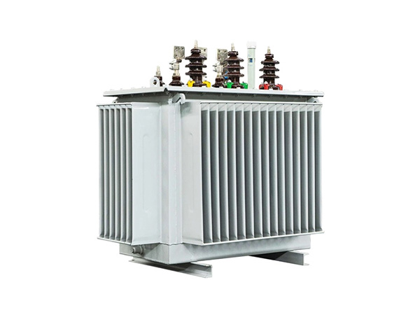
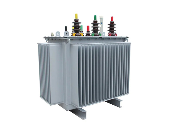
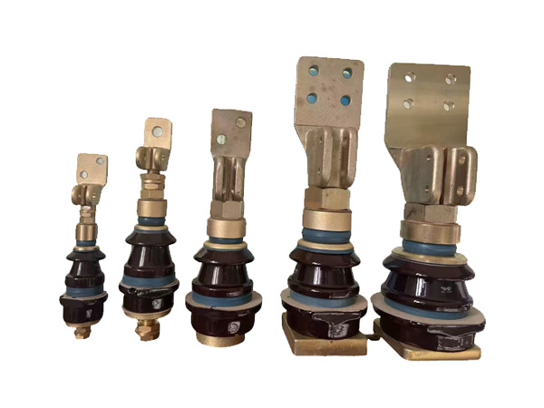
Transformer bushings consistently rank among the most frequently replaced and most dangerous transformer parts in high-voltage equipment. The failure modes are well-understood and, in most cases, detectable through routine condition monitoring long before catastrophic collapse.
Oil-impregnated paper (OIP) bushings degrade through moisture ingress at the sealing flange, partial discharge erosion of the paper insulation, and thermal aging of the oil impregnant. As degradation progresses, the bushing capacitance and dissipation factor drift from factory baseline values. A capacitance change exceeding 2% or a dissipation factor increase exceeding 0.005 from the as-delivered value indicates replacement is warranted. Field data from IEEE transformer reliability studies indicates that bushings above 72.5 kV have a mean replacement interval of 22–28 years, with failure rates increasing sharply after 25 years.
Resin-impregnated paper (RIP) bushings demonstrate lower replacement rates due to their void-free solid insulation, but they are not immune—epoxy delamination, tracking on the silicone rubber sheds of composite designs, and PD activity at the stress grading interface all drive RIP bushing replacements.
Insulating Oil: The Consumable Fluid
Transformer oil is the most actively replaced of all transformer parts. Unlike solid components that fail suddenly, oil degrades predictably, enabling condition-based replacement planning.
The primary degradation mechanisms are oxidation, moisture absorption, and thermal breakdown. Oxidation produces acids that attack paper insulation and metal surfaces. Moisture reduces dielectric breakdown strength—a 0.5% moisture content increase can halve the oil breakdown voltage. Thermal breakdown generates dissolved gases: methane, ethane, and ethylene from paper aging; acetylene from arcing at temperatures exceeding 1000 degrees Celsius.
Replacement thresholds typically include dielectric breakdown below 30 kV per IEEE C57.106, neutralization number exceeding 0.3 mg KOH/g, and interfacial tension below 25 mN/m. Many utilities schedule oil replacement at major transformer overhauls regardless of condition, trading the cost of unnecessary replacement against the risk of degraded oil causing a winding failure.
Tap Changer Components: High-Cycle Wear Parts
On-load tap changer (OLTC) mechanisms are among the most mechanically stressed transformer parts, subjected to thousands of operations per year with arcing contact erosion at each step transition. The diverter switch—the component that actually makes and breaks load current—is a wear item with a defined operational life.
For vacuum switching OLTCs, typical diverter switch life is 150,000–300,000 operations depending on load current magnitude. For resistor-type OLTCs, contact wear is more rapid, with replacement intervals of 50,000–100,000 operations. IEEE C57.131 specifies mechanical and electrical endurance requirements, but actual field performance varies significantly with operating conditions.
Replacement is indicated when tap changer operating time exceeds manufacturer limits, when oil analysis shows elevated C2H2 and CO2 consistent with arcing, or when drive mechanism wear produces irregular step timing. Budget for OLTC overhaul at every second or third transformer major outage cycle.
Gaskets and Seals: Leak-Prevention Parts
Transformer tank gaskets and flange seals are replaced far more frequently than most engineers realize. The rubber and cork compositions used in transformer sealing degrade under thermal cycling, UV exposure, and oil contact, becoming brittle and losing compressibility.
Oil leaks at flange seals account for the majority of oil loss incidents in aging transformers. While individual gasket replacement is a routine field maintenance task, the cumulative maintenance burden becomes significant on transformers with multiple sealing points. Conservative practice replaces all accessible gaskets at major overhauls, accepting some over-maintenance in exchange for eliminating leak risk at aging sealing points.
The conservator tank diaphragm seal, where fitted, degrades more slowly but represents a critical transformer part requiring periodic inspection and replacement on a 15–20 year cycle.
Conservator and Pressure Relief Device Components
The conservator tank itself rarely requires replacement, but its integrated components—the silica gel breather and oil level indicator—require regular replacement as part of routine maintenance.
Silica gel desiccant in breathers exhausts its moisture absorption capacity progressively. When the gel reaches saturation, it turns pink (from cobalt chloride indicator) and must be replaced. In high-humidity environments, replacement intervals can be as short as 3–6 months. Self-indicating gel (orange to green) reduces inspection burden but increases consumable cost.
Pressure relief devices that have activated require immediate replacement of the diaphragm or self-resetting mechanism reset. A PRD that has operated once has demonstrated its design threshold was reached—repeat operation risk is elevated until the device is reset or replaced with a new unit.
Buchholz Relay: Protection Replacement
The Buchholz relay, a gas- and oil-actuated protective device mounted in the pipe between the main tank and conservator, is a transformer part that occasionally requires replacement due to mechanism wear, contact failure, or damage during maintenance.
Common replacement triggers include failed alarm contacts identified during relay testing campaigns, physical damage to the relay housing from corrosion or impact, and age-related degradation of the float mechanism. The relay alarm and trip contacts should be tested annually per IEEE C37.96; failed contacts are replaced individually without replacing the entire relay housing in most designs.
For transformers without integrated online gas monitoring, the Buchholz relay is irreplaceable as the primary early-warning device for developing internal faults. Ensuring its reliable operation is one of the highest-value maintenance investments in oil immersed transformer asset management.
Frequently Asked Questions
What is the most expensive transformer part to replace?
Windings are the most expensive single transformer part to replace, requiring complete disassembly, rewinding, and reassembly at a specialist workshop. Costs for rewinding a 1000 kVA distribution transformer range from $30,000 to $80,000 depending on voltage class. For this reason, winding replacement is typically only economical on transformers with remaining structural life exceeding 15 years. Most transformers are retired rather than rewound once winding failure occurs.
How often should transformer bushings be replaced?
Bushings above 72.5 kV typically require replacement at 22–28 years unless condition monitoring data indicates earlier replacement. Below 36 kV, bushings are replaced on a condition basis rather than age basis. Capacitance and dissipation factor trending provides the most reliable replacement timing indicator.
Can transformer oil be replaced without removing the transformer from service?
Oil can be processed and regenerated in place using mobile filtration and dehydration units, achieving oil quality improvement without outage. Full oil replacement requires draining the tank and refilling—a significant outage—but is performed routinely during transformer overhauls. For transformers without drain valves, top oil replacement through the conservator may be the only in-service option.
What causes tap changers to fail most frequently?
Contact wear from arcing is the dominant failure mechanism in OLTCs. Each tap change produces a small amount of contact erosion; cumulative wear eventually exceeds design limits. Contact wear is accelerated by high load current, frequent operation, and poor oil quality. Regular oil analysis and mechanism timing verification detect wear progression before contact failure occurs.
How do I know when transformer gaskets need replacement?
Visual oil seepage at flange joints is the most obvious indicator. However, by the time visible leaks appear, the gasket has lost significant compressibility and may have been leaking internally for some time. Proactive replacement at major overhauls—replacing all accessible flange gaskets regardless of apparent condition—is the standard practice for transformers older than 15 years.
Conclusion
The transformer parts most likely to require replacement follow a predictable pattern: consumables (oil, silica gel, gaskets) are replaced routinely; wear items (tap changer contacts, pressure relief diaphragms) on a cycle determined by operating conditions; and critical components (bushings, windings) on a condition basis determined by monitoring data. The discipline that separates proactive from reactive transformer management is consistent condition monitoring—annual oil testing, periodic insulation measurements, regular thermal imaging—that generates the data needed to schedule replacements during planned outages rather than forced shutdowns. For B2B maintenance teams, building a 5-year replacement forecast based on component age, condition trends, and manufacturer service life data is the foundation of a cost-effective transformer asset management program.
References
CIGRE Working Group A2.37, "Transformer Reliability Survey," Technical Brochure 542, 2015.
IEEE Std C57.106-2015, "Guide for Acceptance and Maintenance of Insulating Oil in Equipment," IEEE Power & Energy Society.
IEEE Std C57.131-2012, "IEEE Standard Requirements for On-Load Tap Changers," IEEE Power & Energy Society.
IEEE Std C57.19.01-2017, "Standard Performance Characteristics and Dimensions for Outdoor Apparatus Bushings," IEEE Power & Energy Society.
Kulkarni, S.V., & Khaparde, S.A., "Transformer Engineering: Design, Technology, and Diagnostics," CRC Press, 2012.
MORE
-
How to Choose the Right Dry Type Transformer Capacity
2026-08-18
-
How to Source Reliable Transformer Parts Suppliers
2026-08-12
-
Pressure Relief Device Testing and Maintenance Guide
2026-08-12
-
Oil Immersed Transformer Maintenance Best Practices Guide
2026-08-12
-
Common Causes of Transformer Bushing Failure and Prevention
2026-08-12