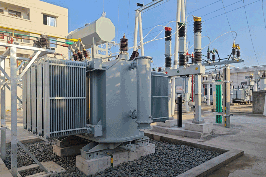






Signs Your Transformer Oil Level Indicator Needs Replacement
Time:2026-07-11 15:42:20 Author:zhongbei Click:95
The oil level indicator is one of the most visually accessible components on any oil immersed transformer, yet its failure is frequently misdiagnosed or overlooked until it contributes to a more serious incident. When an oil level indicator fails, the operator loses the primary tool for detecting oil loss—a condition that, if left unaddressed, can progress to partial discharge, winding failure, and tank rupture. This article focuses specifically on identifying when an oil level indicator requires replacement, the root causes behind common failure modes, and the replacement procedures that restore reliable monitoring to the transformer asset.
Why Oil Level Indicators Fail
Understanding the mechanisms behind oil level indicator failure enables more accurate diagnosis and appropriate replacement decisions. The most common root causes are environmental, mechanical, and material degradation operating over extended service periods.
Thermal cycling is the primary driver of mechanical failure. As the transformer cycles through load and ambient temperature variations, the float inside the conservator experiences repeated thermal expansion and contraction stresses. The brazed or welded joints that seal the float shell are particularly susceptible to fatigue failure under thermal cycling, leading to oil ingress into the float cavity. Once oil penetrates the float, buoyancy is progressively lost until the float sinks entirely, reading zero regardless of actual oil level.
Magnetic coupling degradation is a second major failure mechanism. The magnet inside the float drives the indicator needle through a non-magnetic hermetic barrier. Over 15–25 years of thermal cycling, magnet strength decays—neodymium magnets lose approximately 1–2% of their flux density per decade at operating temperatures. Weakened magnetic coupling produces sluggish needle response, failure to reach full-scale deflection, and ultimately complete decoupling from the float position.
Five Signs Your Oil Level Indicator Needs Replacement
Sudden complete loss of indicator response is among the most unmistakable failure signs. If the needle drops to zero without corresponding ambient temperature change, the most likely cause is float sinking from internal oil ingress. Do not continue operating the transformer on the assumption that the oil level is actually normal—use a dipstick measurement or ultrasonic tank level gauge to confirm actual oil level before making that determination. Float sinking is an immediate replacement indicator.
Progressive drift from expected level over multiple inspection cycles, despite consistent ambient temperatures and load profiles, suggests the magnetic coupling is weakening or the float arm is binding against conservator wall deposits. Drift exceeding one graduation mark per year on the indicator dial warrants investigation and likely oil level indicator replacement before the next inspection cycle.
Physical damage to the indicator housing—cracked dial face from impact or UV degradation, condensation under the window obscuring the reading, or corrosion on the external housing from outdoor exposure—compromises the indicator reliability regardless of internal mechanism condition. Replace damaged housings at the next convenient outage rather than waiting for a more serious failure.
Erratic or inconsistent readings that vary between inspection visits without corresponding temperature or load changes indicate mechanical binding or intermittent magnetic coupling failure. An oil level indicator that jumps between positions or sticks at intermediate positions is providing unreliable data and should be treated as a failed instrument requiring oil level indicator replacement.
Trend data comparison reveals drift that single-point readings miss. When the historical oil level trend shows a sudden step change that does not correspond to any known oil addition or removal, the indicator mechanism itself is suspect. Comparing indicator reading against actual measured oil volume using a calibrated tank gauge on the same day confirms whether the discrepancy is in the indicator or the oil inventory.
Replacement Procedure Overview
Replacing an oil level indicator on an energized transformer is not recommended due to electrical safety hazards. Replacement should occur during a planned de-energized outage with the transformer in a safe condition for access to the conservator.
The replacement procedure follows a standard sequence. First, drain oil to below the conservator connection level or use a containment dam to prevent oil spillage. Second, remove the old indicator from its mounting flange, noting the gasket arrangement and bolt torque specifications. Third, inspect the float mechanism inside the conservator for physical condition and verify that the new indicator float matches the conservator dimensions. Fourth, install the new indicator with new sealing gaskets, applying manufacturer-specified torque to the mounting bolts. Fifth, refill oil to the correct level, verify the indicator reading against known oil volume, and record the baseline for future trend monitoring.
Selecting the Correct Replacement Indicator
Replacement indicator selection must match the original specification in several key dimensions. The mounting flange dimensions must be compatible—different manufacturers use different flange sizes and bolt patterns. The float displacement and weight rating must be appropriate for the conservator oil volume and density. The temperature range must cover the transformer worst-case ambient conditions without mechanical failure. The indication range and calibration marks must correspond to the transformer rated oil volume and expansion range.
When the original manufacturer is no longer available or the specific model has been discontinued, universal replacement indicators are available from specialist transformer accessory suppliers. Verify compatibility by comparing rated oil volume, temperature range, and flange dimensions against the original specification before ordering.
Maintenance Practices to Extend Indicator Life
While oil level indicator replacement is unavoidable on transformers approaching 20 years of age, proper maintenance can extend reliable service life and reduce premature failures. Annual visual inspection checking for housing damage, condensation, and oil seepage at the mounting flange identifies problems early. Periodic comparison of indicator readings against physical oil level measurements establishes a calibration accuracy baseline. Ensuring that the conservator breather remains functional and the desiccant is not saturated prevents moisture accumulation inside the conservator that can corrode the float mechanism.
Frequently Asked Questions
Can I replace just the float mechanism instead of the entire oil level indicator?
In some designs, the float mechanism can be replaced independently of the external indicator and dial assembly. However, this requires draining oil to expose the conservator internals, which is a significant outage. In most cases, complete oil level indicator replacement during a planned outage is more cost-effective than partial repair, particularly when the outage is already scheduled for other maintenance activities.
How long does an oil level indicator typically last?
A well-maintained oil level indicator typically provides 20–30 years of reliable service. Float sinking and magnetic coupling degradation become increasingly likely after 20 years. On transformers exceeding 20 years of age, budgeting for oil level indicator replacement as part of the next major overhaul is prudent asset management.
What should I do if the indicator shows critically low oil?
First, verify actual oil level using a dipstick or ultrasonic tank gauge—do not rely solely on the indicator reading if failure is suspected. If oil level is confirmed critically low, initiate the transformer emergency response procedure. Continuing to operate a transformer with critically low oil creates immediate risk of internal fault, tank rupture, and fire.
Are electronic oil level indicators more reliable than magnetic float types?
Electronic oil level indicator systems using capacitance or ultrasonic sensors generally provide longer mean time between failures than mechanical float indicators, primarily because they have no moving parts exposed to the oil environment. However, they require power supply and are more expensive. The reliability advantage is most significant on critical transformers where missed oil loss events have high consequences.
Does oil color affect indicator accuracy?
Oil color change from aging or contamination does not directly affect float buoyancy or magnetic coupling accuracy. However, dark-colored aged oil can obscure the sight glass on direct-reading indicators, making visual level confirmation difficult. The magnetic float indicator is unaffected by oil color since it operates by buoyancy rather than optical sighting.
Conclusion
The oil level indicator is a component that earns attention primarily when it fails to perform. Maintaining a schedule of regular inspection, periodic calibration verification against physical oil volume, and proactive replacement at 20–25 years of age ensures continuous reliable monitoring throughout the transformer service life. When replacement is required, selecting a compatible unit matched to the conservator dimensions and operating conditions—and performing the replacement during a planned outage rather than an emergency—is the discipline that distinguishes mature transformer asset management from reactive firefighting. An accurate, functional oil level indicator is inexpensive insurance against the much larger costs of oil-related transformer failure.
References
IEEE Std C57.106-2015, "Guide for Acceptance and Maintenance of Insulating Oil in Equipment," IEEE Power & Energy Society.
IEC 60247:2004, "Insulating Liquids – Measurement of Relative Permittivity, Dielectric Dissipation Factor (tan d) and d.c. Resistivity," International Electrotechnical Commission.
CIGRE Working Group A2.37, "Transformer Reliability Survey," Technical Brochure 542, 2015.
Kulkarni, S.V., & Khaparde, S.A., "Transformer Engineering: Design, Technology, and Diagnostics," CRC Press, 2012.
Pansini, A.J., "Power Transformer Fundamentals," Fairmont Press, 2018.
MORE
-
Transformer Components Most Likely to Require Replacement
2026-07-24
-
Signs Your Transformer Oil Level Indicator Needs Replacement
2026-07-11
-
dry-type-transformers-for-commercial-buildings
2026-07-11
-
DIN Standard Porcelain Bushings: Features and Benefits
2026-07-11
-
Copper vs Aluminum Terminal Studs for Transformers
2026-07-11