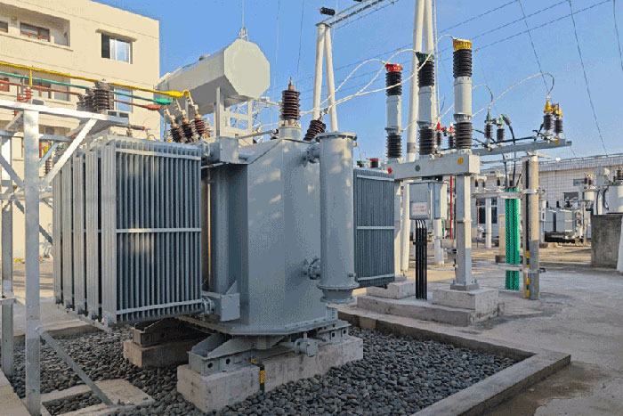
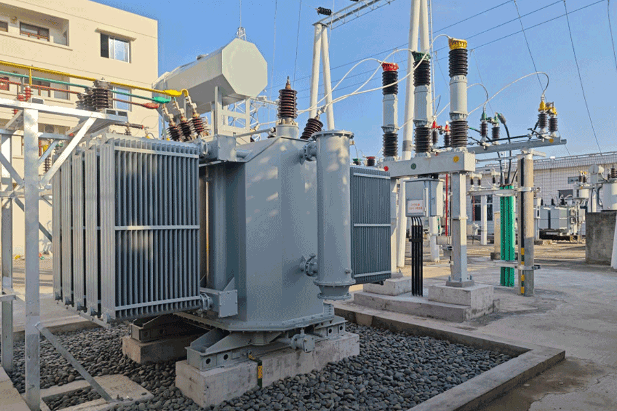






Essential Transformer Parts and Their Functions
Time:2026-06-17 15:58:20 Author:zhongbei Click:77
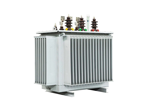
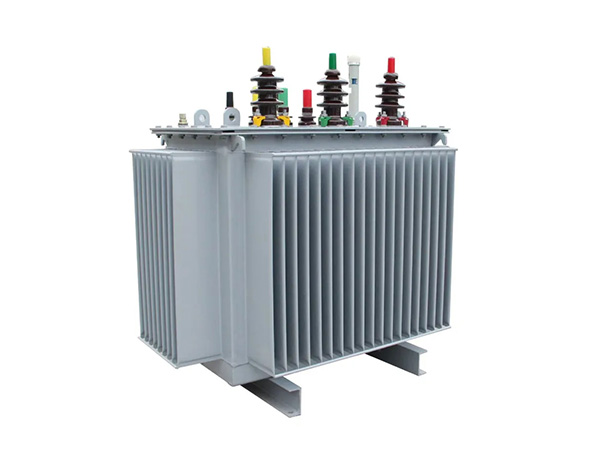
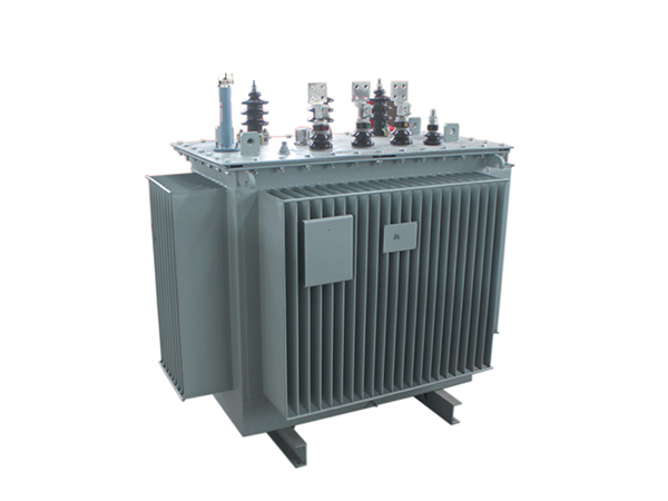
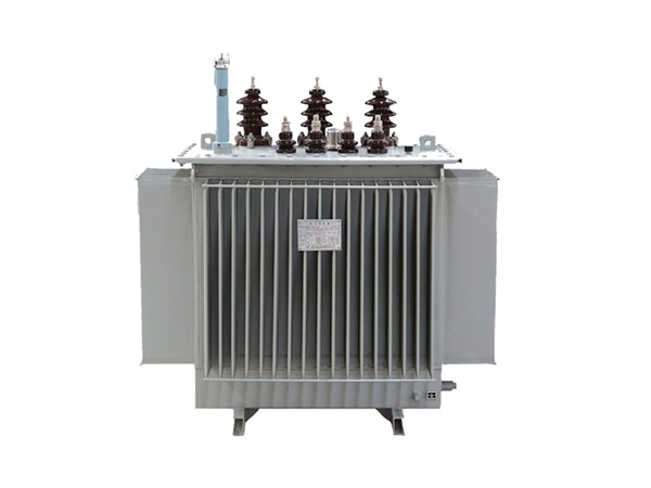
Understanding the individual components of a transformer is fundamental to proper specification, installation, and maintenance. Whether procuring a new unit, troubleshooting a field problem, or planning a maintenance program, B2B technical teams benefit from a clear understanding of how each transformer part contributes to overall device performance. This guide provides a systematic overview of essential components in both oil-immersed and dry type designs, with practical guidance on specification criteria and failure modes.
Core: The Magnetic Circuit
The transformer core forms the magnetic circuit that links primary and secondary windings. Core material and construction directly impact efficiency, no-load losses, and audible noise:
Material: Grain-oriented silicon steel (CRGO) is standard, offering low core loss. Amorphous metal cores achieve 60–70% lower no-load loss but at higher cost and with mechanical fragility constraints.
Construction: Core-type designs (windings surround the core limbs) dominate for distribution and power transformers. Shell-type designs (core surrounds the windings) are used for special applications requiring high mechanical strength.
Lamination: Thin laminations (0.23–0.30 mm) reduce eddy current losses. Laser-scribed or domain-refined grades further reduce losses at the expense of increased cost.
Failure modes: Core overheating from circulating currents in the tank or frame, insulation breakdown between laminations, and mechanical damage during transport can all degrade performance. Infrared thermography during commissioning identifies abnormal core hot spots.
Specifiers should require core loss certificates and audible noise guarantees, particularly for installations in noise-sensitive environments.
Windings: The Electrical Circuit
Windings carry the primary and secondary currents and are the most stressed transformer part under fault conditions:
Conductor material: Copper windings offer higher conductivity and mechanical strength; aluminum windings are lighter and lower cost but require larger cross-section for equivalent current rating.
Winding arrangement: Concentric windings (high voltage outside, low voltage inside) are standard. Interleaved windings reduce leakage reactance for applications requiring low impedance.
Insulation: Oil-impregnated paper (OIP) for oil-immersed units; epoxy resin or varnish for dry type. Insulation class (F, H) determines maximum operating temperature.
Failure modes: Turn-to-turn faults from insulation degradation, winding deformation from through-fault mechanical forces, and overheating from overloading or blocked cooling.
For critical applications, specify partial discharge measurement during factory testing and require winding resistance measurement at tap positions to verify uniform contact resistance.
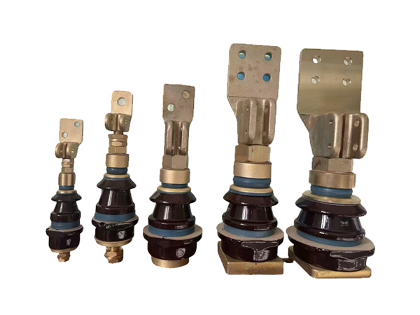
Bushings: High-Voltage Connections
Bushings provide insulated passages for conductors to enter and exit the transformer tank. As a critical transformer part, bushing failures account for approximately 15–20% of transformer failures in industry surveys:
Oil-impregnated paper (OIP) bushings: Standard for 66 kV and below. Lower cost but require periodic oil level inspection and are susceptible to moisture ingress.
Resin-impregnated paper (RIP) bushings: Dry-type construction, inherently moisture-resistant. Preferred for 132 kV and above, and for harsh environments. Higher first cost but reduced maintenance.
Failure modes: Partial discharge leading to insulation breakdown, oil leakage in OIP types, cracked porcelain from mechanical impact or thermal shock, and contaminated oil surfaces causing flashover.
Regular infrared scanning of bushings during peak load identifies developing hot spots before failure. Specify tan delta and capacitance measurement during routine testing.
Tap Changer: Voltage Regulation
The tap changer enables voltage ratio adjustment to compensate for grid voltage variations or load conditions:
Off-circuit tap changer (OCTC): Requires de-energization to change taps. Standard for distribution transformers with infrequent adjustment needs. Lower cost and higher reliability.
On-load tap changer (OLTC): Adjusts taps under load without interrupting service. Essential for transformers feeding variable loads or compensating for significant grid voltage variation. Higher maintenance requirement.
Failure modes: Contact wear and burning in OLTC units, mechanism jamming, oil contamination in diverter switch compartment, and synchronization failures between phases.
For OLTC-equipped transformers, budget for diverter switch maintenance at 100,000–150,000 operations and require OLTC condition monitoring through motor current signature analysis.
Conservator and Oil Preservation System
The conservator and associated components manage oil expansion and prevent contamination:
Conservator tank: Provides expansion volume for oil as temperature rises. Maintains positive oil pressure on the main tank, preventing air ingress at seals.
Silica gel breather: Dries incoming air as oil level rises and falls with temperature cycling. Silica gel changes color (blue to pink) when saturated, indicating replacement need.
Oil level indicator: Magnetic or float-type gauge indicates oil level. Sudden level changes signal leaks or internal problems.
Failure modes: Saturated or depleted desiccant allowing moisture into oil, blocked breather creating vacuum conditions, and indicator malfunction masking actual oil loss.
Monthly inspection of breather condition and oil level is a low-cost, high-value maintenance activity for the oil immersed transformer.
Buchholz Relay: Internal Fault Protection
The Buchholz relay is a protective device unique to oil immersed transformer designs with conservators:
Function: Mounted in the pipe between main tank and conservator, the relay detects gas accumulation (from internal faults) and oil surge (from major internal arcing).
Alarm and trip contacts: Gas accumulation triggers alarm; oil surge trips the transformer circuit breaker. Provides early warning of developing internal faults.
Testing: Annual testing by injecting air through the test valve verifies relay operation. Neglecting this simple test has led to preventable transformer failures.
The Buchholz relay provides protection that no external relay can match—detecting slow-developing faults such as incipient winding shorts before they escalate to catastrophic failure.
Cooling System: Radiators and Fans
The cooling system dissipates heat generated by core and winding losses:
Radiators: Finned panels attached to the tank provide surface area for heat transfer. Mounted directly on small transformers; separate banks for larger units.
Cooling fans: Axial fans force air across radiators, increasing cooling capacity by 25–35%. Automatic control via top-oil temperature or winding temperature indicators.
Oil pumps: For OFAF designs, pumps circulate oil through external heat exchangers. Add maintenance complexity but enable compact installation.
Failure modes: Blocked airflow from debris accumulation, fan motor failure, pump seal leaks, and radiator fin damage from corrosion or mechanical impact.
Clean radiators annually in dusty environments. Verify fan operation during commissioning and at routine intervals—stuck fans lead to transformer overheating under peak loading.
Protective Devices and Monitoring
Modern transformer part specifications increasingly include monitoring and protection devices:
Winding temperature indicator (WTI): Simulates hotspot temperature by combining top-oil temperature with a heating element proportional to load current. Critical for overload protection.
Pressure relief device (PRD): Relieves excessive internal pressure from internal faults, preventing tank rupture. Self-resetting diaphragm type is standard.
Gas-in-oil monitor: Online DGA monitoring for critical transformers provides continuous fault gas measurement, enabling early intervention.
Dissolved moisture sensor: Monitors water content in oil, alerting when moisture exceeds acceptable levels.
For high-value assets, specifying comprehensive monitoring pays dividends through early fault detection and optimized maintenance scheduling.
Frequently Asked Questions
What is the most critical transformer part to monitor?
The windings and insulation system are the most critical. Winding temperature and dissolved gas analysis provide the best indicators of winding health. Monitor these parameters closely for early warning of developing problems.
How often should tap changers be maintained?
OLTC diverter switches require oil filtration or replacement at 100,000–150,000 operations. Contacts typically need inspection at 200,000–300,000 operations. OCTC units require only periodic inspection during transformer outages.
What causes bushing failures?
The primary causes are partial discharge degradation, moisture ingress in OIP bushings, mechanical damage to porcelain, and contaminated external surfaces. Regular infrared scanning and periodic tan delta testing identify developing problems.
Can a Buchholz relay detect all internal faults?
No. Buchholz relays detect faults that generate gas or cause oil surge—primarily internal arcing and severe overheating. They do not detect turn-to-turn faults at incipient stages. Complementary protection through differential relays and DGA monitoring is required for comprehensive coverage.
How does amorphous core material affect transformer parts selection?
Amorphous cores are more brittle than CRGO steel, requiring careful mechanical design to avoid core damage during assembly and transport. This may influence tank design, core clamping structures, and handling procedures—all transformer parts and processes require adaptation.
Conclusion
Each transformer part plays a defined role in the overall performance and reliability of the asset. For procurement professionals, understanding these roles enables better specification—matching component quality and features to application requirements. For maintenance teams, component-level knowledge supports targeted inspection programs, early fault detection, and informed repair-versus-replace decisions. The transformer's long service life—30–40 years for well-maintained units—makes proper specification and maintenance of individual parts a high-value investment. When specifying transformers, require detailed component data sheets and test certificates. When maintaining transformers, focus inspection and testing resources on the failure-prone components: bushings, tap changers, and the insulation system. This disciplined approach maximizes asset reliability and lifecycle value.
References
IEEE Std C57.12.10-2020, "General Requirements for Liquid-Immersed Power Transformers," IEEE Power & Energy Society.
IEC 60076-3:2018, "Power Transformers – Part 3: Insulation Levels, Dielectric Tests and External Clearances," International Electrotechnical Commission.
CIGRE Working Group A2.37, "Transformer Reliability Survey," Technical Brochure 542, 2015.
IEEE Std C57.131-2012, "IEEE Standard Requirements for On-Load Tap Changers," IEEE Power & Energy Society.
Kulkarni, S.V., & Khaparde, S.A., "Transformer Engineering: Design, Technology, and Diagnostics," CRC Press, 2012.
MORE
-
Transformer Components Most Likely to Require Replacement
2026-07-24
-
Signs Your Transformer Oil Level Indicator Needs Replacement
2026-07-11
-
dry-type-transformers-for-commercial-buildings
2026-07-11
-
DIN Standard Porcelain Bushings: Features and Benefits
2026-07-11
-
Copper vs Aluminum Terminal Studs for Transformers
2026-07-11