





Common Causes of Transformer Bushing Failure and Prevention
Time:2026-08-12 14:58:58 Author:zhongbei Click:55
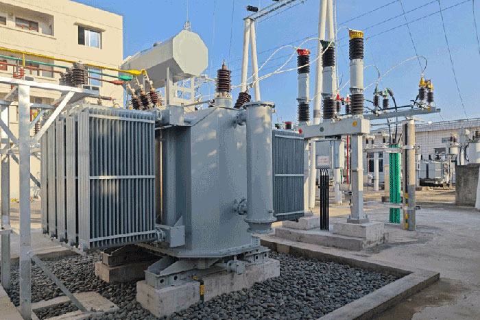
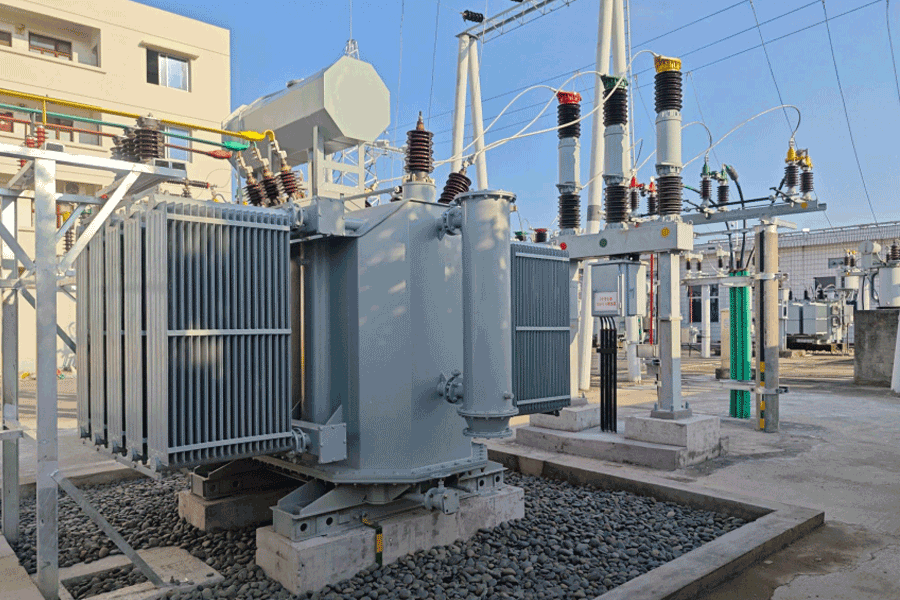
Among all components on a power transformer, bushings rank as both the most failure-prone and the most dangerous when they fail. A porcelain bushing that collapses under fault conditions can spray oil, generate explosive pressure, and create arc flashes that threaten personnel safety and adjacent equipment. Industry reliability surveys consistently identify bushings as a leading cause of forced transformer outages. Understanding the mechanisms behind transformer bushing failure enables maintenance teams to detect developing problems early and prevent catastrophic events.
Moisture Ingress Through Sealing System Deterioration
The most prevalent cause of transformer bushing failure involves moisture entering the bushing insulation system through degraded seals. Oil-impregnated paper bushings, the dominant technology for high-voltage applications, depend on the hermetic integrity of sealing gaskets at the mounting flange, oil expansion chamber, and terminal connections.
Sealing materials degrade over time through thermal cycling, ozone exposure, and chemical attack from oil oxidation products. As gaskets lose elasticity, they develop micro-gaps that allow atmospheric moisture to penetrate the bushing interior. Moisture migration accelerates under thermal cycling—the pressure differentials created by temperature changes draw humid air inward through seal imperfections.
Once moisture enters the insulation system, it dramatically reduces dielectric strength. Water migrates to the highest electrical stress regions—typically the central conductor area and the stress grading layers. Partial discharge activity initiates at these wetted locations, eroding paper insulation and generating additional degradation products. The failure progression can span years, providing multiple opportunities for detection through condition monitoring.
Partial Discharge Erosion of Insulation
Partial discharge represents localized electrical breakdown within insulation systems that does not immediately bridge the electrodes. In porcelain bushings, partial discharge occurs at locations where electrical stress exceeds the local dielectric strength—typically at voids, contaminants, moisture accumulation sites, or stress grading interfaces.
Each partial discharge pulse creates a small but cumulative degradation event. The discharge erodes paper insulation, decomposes oil, and generates gaseous byproducts that create additional voids. Over time, these individual degradation events combine into progressively larger damaged zones. The erosion process accelerates as damaged zones expand and electrical stress concentration increases.
Detecting partial discharge before it progresses to failure requires specialized measurement techniques. On-line partial discharge monitoring systems detect discharge activity during normal operation. Off-line tests measure partial discharge inception voltage and magnitude at elevated test voltages. Both approaches provide early warning of developing transformer bushing failure from discharge erosion.
Thermal Aging of Insulation Materials
Transformer bushings operate at elevated temperatures due to conductor current heating and exposure to transformer top oil. Over decades of service, the insulation materials undergo thermal aging that progressively reduces mechanical and dielectric properties.
Oil-impregnated paper insulation ages according to temperature-dependent chemical reactions. Higher temperatures accelerate aging—the same Arrhenius relationship that governs transformer winding insulation applies to bushing paper. Bushings located near transformer hot spots or carrying high continuous currents experience faster thermal aging than those in cooler locations with lighter loading.
Thermal aging manifests as increased dissipation factor and changed capacitance values. These parameters reflect insulation condition and provide trending indicators for replacement planning. A bushing that shows steadily increasing dissipation factor over successive measurements is experiencing insulation deterioration that will eventually result in failure if not addressed.
Mechanical Damage and External Contamination
Bushings face mechanical stresses from multiple sources. Conductor connection forces apply cantilever loads to the bushing structure. Wind and seismic loads transmit through the conductor and terminal hardware. Transportation and installation activities create handling stresses if proper procedures are not followed.
Mechanical damage to porcelain bushing exteriors creates stress concentrations that can initiate crack propagation. Surface glaze damage from impact or erosion exposes the porous ceramic substrate to contamination and moisture absorption. Cracks that penetrate through the porcelain wall create direct leakage paths for oil and entry points for moisture.
External contamination from industrial environments deposits conductive films on bushing surfaces. Salt spray in coastal locations, chemical emissions in industrial areas, and dust accumulation in desert environments all create contamination layers that promote surface tracking and flashover. Regular cleaning prevents contamination buildup from reaching critical densities that initiate surface failure.
Oil Degradation Within the Bushing
Bushings contain their own oil volume separate from the main transformer tank. This oil serves as electrical insulation and thermal transfer medium within the bushing structure. Like transformer main tank oil, bushing oil degrades over time through oxidation, moisture absorption, and thermal decomposition.
Bushing oil condition can be assessed through sampling ports on some designs, though sampling requires careful procedures to avoid introducing contamination. Dissolved gas analysis of bushing oil detects incipient faults just as it does for main tank oil. Elevated hydrogen and methane levels indicate partial discharge activity within the bushing insulation system.
For bushings without sampling capability, condition assessment relies on external measurements—capacitance, dissipation factor, and partial discharge detection. These indirect methods provide less specific information than direct oil analysis but remain valuable for trending bushing condition over time.
Stress Grading System Deterioration
High-voltage bushings incorporate stress grading systems that control electric field distribution along the bushing length. These systems use resistive grading layers, capacitive grading foils, or combination approaches to prevent excessive electrical stress concentration.
Stress grading materials are subject to their own degradation mechanisms. Resistive grading layers can drift in resistance value over time, altering field distribution. Capacitive grading layers can develop partial discharge at layer edges or at voids within the grading structure. Grading system deterioration produces measurable changes in bushing capacitance and partial discharge behavior.
Field experience indicates that stress grading problems often develop in older bushings that have passed their design life. Bushings approaching or exceeding 25 years of service warrant increased monitoring frequency and careful evaluation of any measured parameter changes.
Prevention Through Condition Monitoring
Preventing transformer bushing failure requires systematic condition monitoring that detects degradation before failure. The most effective programs combine multiple monitoring techniques to provide comprehensive condition awareness.
Capacitance and dissipation factor measurements at regular intervals track insulation condition trends. Measure these parameters annually or biennially at minimum, with increased frequency for bushings showing concerning trends or those exceeding 20 years of age. Establish baseline values during commissioning and compare subsequent measurements against these baselines rather than generic acceptance criteria.
Partial discharge monitoring provides direct detection of the degradation mechanism responsible for many bushing failures. On-line systems monitor continuously during operation, detecting intermittent discharge activity that might be missed by periodic testing. Off-line partial discharge tests quantify discharge magnitude and inception voltage for trending analysis.
Infrared thermography during peak load periods detects abnormal heating in bushing connections and stress grading regions. Temperature anomalies indicate high-resistance connections, grading system deterioration, or internal problems requiring investigation. Thermal imaging also identifies oil circulation problems in forced-oil cooled bushings.
Frequently Asked Questions
How long do transformer bushings typically last?
Well-maintained bushings in moderate operating conditions typically achieve 25 to 35 years of service life. Bushings in harsh environments, those with high thermal loading, or those experiencing manufacturing defects may fail earlier. Bushings exceeding 25 years warrant increased monitoring attention regardless of apparent condition.
What are the warning signs of bushing failure?
Warning signs include oil leakage at seals, visible damage or contamination on porcelain surfaces, increasing capacitance or dissipation factor measurements, elevated partial discharge levels, abnormal thermal patterns in infrared surveys, and audible noise during operation. Any of these indicators warrants immediate investigation.
Can bushings be repaired or must they be replaced?
Most bushing problems require complete replacement rather than repair. Gasket replacements and external cleaning address some issues, but internal insulation degradation, partial discharge damage, and stress grading deterioration cannot be economically repaired in the field. Bushing replacement during planned outages prevents the much higher costs of forced outages from bushing failure.
What causes catastrophic bushing explosions?
Catastrophic failures occur when internal degradation progresses to complete insulation breakdown at high electrical stress locations. The resulting arc vaporizes oil and generates explosive pressure within the bushing. If the mechanical structure fails to contain this pressure, the bushing ruptures violently. Proper condition monitoring detects degradation before it reaches the failure threshold.
How do I determine the appropriate monitoring frequency for bushings?
Base monitoring frequency on bushing age, operating conditions, criticality, and previous measurement results. Annual capacitance and dissipation factor measurements are standard for healthy bushings. Increase frequency to every six months for bushings over 20 years old, those in harsh environments, or those showing concerning trends. Apply continuous partial discharge monitoring to critical transformers where bushing failure would have severe consequences.
Conclusion
Transformer bushing failure results from multiple degradation mechanisms that develop over years of service. Moisture ingress, partial discharge erosion, thermal aging, mechanical damage, oil degradation, and stress grading deterioration each contribute to the failure modes observed in service. The common factor across these mechanisms is that degradation progression creates measurable changes detectable through systematic condition monitoring. Preventing bushing failures requires measurement programs that track these indicators, trending analysis that identifies developing problems, and proactive replacement before degradation progresses to failure. The investment in condition monitoring and timely bushing replacement is modest compared to the costs of forced outages, equipment damage, and safety incidents that result from bushing failures.
References
IEEE Std C57.19.01-2017, "Standard Performance Characteristics and Dimensions for Outdoor Apparatus Bushings," IEEE Power & Energy Society.
IEC 60137:2017, "Insulated Bushings for Alternating Voltages Above 1000 V," International Electrotechnical Commission.
CIGRE Working Group A2.37, "Transformer Reliability Survey," Technical Brochure 542, 2015.
Kulkarni, S.V., and Khaparde, S.A., "Transformer Engineering: Design, Technology, and Diagnostics," CRC Press, 2012.
IEEE Std C57.113-2010, "Recommended Practice for Partial Discharge Measurement," IEEE Power & Energy Society.
MORE
-
How to Choose the Right Dry Type Transformer Capacity
2026-08-18
-
How to Source Reliable Transformer Parts Suppliers
2026-08-12
-
Pressure Relief Device Testing and Maintenance Guide
2026-08-12
-
Oil Immersed Transformer Maintenance Best Practices Guide
2026-08-12
-
Common Causes of Transformer Bushing Failure and Prevention
2026-08-12