





Pressure Relief Device Testing and Maintenance Guide
Time:2026-08-12 15:32:02 Author:zhongbei Click:101
The pressure relief device on an oil-filled transformer serves as the final protective barrier against the most catastrophic failure mode—tank rupture from internal pressure buildup. Unlike protective relays that operate frequently during electrical faults, the PRD may sit inactive for decades before being called upon to function. This infrequent operation creates a particular maintenance challenge: how do you verify that a device will work when it has never operated and may never operate during its service life? This guide presents the testing and maintenance practices that ensure pressure relief device reliability despite the long intervals between actual operations.
Understanding PRD Function and Failure Modes
Before establishing maintenance practices, maintenance personnel must understand how pressure relief devices function and what failure modes they can develop. The most common PRD designs use either rupture diaphragms or spring-loaded valves.
Diaphragm-type devices seal the tank opening with a membrane designed to burst at a specified pressure. The diaphragm material—typically silicone-coated fabric or metal foil—remains intact under normal operating pressures but ruptures rapidly when tank pressure exceeds the set point. Once ruptured, the diaphragm cannot reseal; the tank remains open until the diaphragm is replaced.
Spring-loaded valve designs use mechanical pressure against a spring-loaded seal. When tank pressure exceeds the spring force, the valve opens to relieve pressure. Many spring-loaded designs automatically reseal when pressure returns to normal, though some require manual reset. The mechanical complexity of spring-loaded valves creates more potential failure modes than simple diaphragms, but the reset capability reduces oil loss during minor pressure excursions.
Common failure modes include set pressure drift from spring relaxation or diaphragm material aging, seal deterioration allowing minor oil leakage, mechanical binding that prevents full opening, and failure to reseal after operation. Each failure mode has different consequences—set pressure drift might prevent operation when needed, while seal deterioration causes continuous oil loss that creates environmental and safety hazards.
Visual Inspection Procedures
Regular visual inspection forms the foundation of pressure relief device testing and maintenance programs. These inspections identify external problems that could affect device operation.
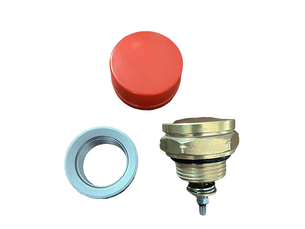
Inspect the device exterior for physical damage, corrosion, and oil leakage. Damage to the vent deflector or rain shield can obstruct the discharge path, reducing flow capacity during operation. Corrosion at mounting flanges or fasteners can weaken structural integrity and prevent proper resealing. Oil residue around the device indicates either past operation or ongoing seal leakage—either condition warrants investigation.
For diaphragm-type devices with visible indicator pins or flags, verify that the indicator shows the unoperated position. A deployed indicator confirms previous operation that may not have been documented. Review operating records and question shift personnel to determine what event triggered operation.
Examine the discharge path direction and verify it remains unobstructed. Equipment additions, structural modifications, or storage of materials near the transformer can block the intended discharge path. Blocked discharge reduces the effectiveness of pressure relief and may redirect oil spray onto equipment or personnel areas.
Set Pressure Verification Testing
The critical parameter for any pressure relief device is the pressure at which it begins to open. Set pressure verification testing confirms that the device will operate within specification when needed.
Field testing of installed devices requires careful procedures to avoid accidental operation during testing. The most common approach applies controlled pressure to the device using a calibrated test pump connected to the tank through a temporary fitting. Pressure increases slowly while monitoring gauges record the pressure at which the device begins to open.
Compare the measured opening pressure against the manufacturer specification and the original commissioning value. Allowable tolerance varies by manufacturer but typically ranges from plus or minus 5 to 10 percent of the set pressure. Devices operating outside tolerance require adjustment, repair, or replacement depending on the nature of the discrepancy.
Set pressure verification testing requires tank isolation and careful safety procedures. The applied test pressure stresses tank components and seals—uncontrolled over-pressurization during testing could cause damage. Follow manufacturer testing procedures precisely and use calibrated pressure gauges appropriate for the expected pressure range.
Seal Integrity Assessment
A pressure relief device that leaks continuously creates environmental contamination, fire hazard from oil accumulation, and eventual transformer low-oil conditions if the leak goes undetected. Seal integrity assessment identifies these problems before they become severe.
For devices with accessible seals, visual inspection during de-energized maintenance periods allows assessment of seal condition. Look for hardened or cracked sealing surfaces, signs of compression set that indicate seal material has lost elasticity, and contamination that could prevent proper seating.
Pressure decay testing provides quantitative assessment of seal integrity. Apply a controlled pressure to the sealed device and monitor pressure over time. Rapid pressure decay indicates seal leakage. Compare decay rates against manufacturer specifications or baseline measurements from previous tests.
For devices with known seal problems, replacement seals are available from manufacturers for many common PRD models. Seal replacement typically requires removing the device from the transformer, replacing seals in a clean environment, and reinstalling with proper torque on mounting fasteners. Document seal replacement in maintenance records.
Electrical Contact Verification
Most pressure relief devices include alarm contacts that energize when the device operates. These contacts provide SCADA indication of operation and often trip transformer breakers to de-energize the transformer before pressure builds further. Contact reliability is critical for protective function.
Test alarm contact operation during maintenance periods by simulating the contact closure through the device mechanism. For devices with test levers or buttons, exercise the mechanism and verify contact operation at the SCADA system. For devices without built-in test features, contact testing may require manual operation of the device mechanism during de-energized maintenance.
Verify contact rating adequacy for the connected circuit. Contacts rated for lower currents than the circuit requires may weld during operation, preventing proper alarm indication. Review circuit design and compare against contact ratings in manufacturer documentation. Upgrade contact ratings if needed through manufacturer modifications or relay interposing.
Documentation and Record Keeping
Comprehensive documentation supports pressure relief device testing and maintenance program effectiveness. Records enable trending analysis, demonstrate regulatory compliance, and support failure investigations.
Maintain records of all inspections, tests, and maintenance activities for each device. Include visual inspection findings, set pressure test results with measured values and tolerances, seal condition assessments, electrical contact test results, and any corrective actions taken. Compare current results against previous measurements to identify trends indicating developing problems.
Document the manufacturer, model number, set pressure, and rated flow capacity for each installed device. This information enables proper replacement part ordering and supports engineering evaluation of device adequacy for the transformer application.
Replacement Planning and Life Cycle Management
Like all mechanical devices, pressure relief devices have finite service life. Planning for replacement ensures devices are replaced before age-related degradation compromises reliability.
Manufacturer recommendations typically specify device service life in the range of 20 to 30 years under normal conditions. Devices in harsh environments—high temperature, chemical exposure, or coastal salt spray—may require earlier replacement. Track device installation dates and schedule replacement as devices approach manufacturer recommended service life.
Consider proactive replacement during planned transformer outages rather than waiting for devices to fail. The cost of a scheduled replacement during a planned outage is far less than the cost of an unplanned outage caused by PRD failure or the consequences of a PRD failing to operate when needed.
Compliance With Standards and Regulations
Various standards and regulations govern pressure relief device requirements and testing. Familiarity with applicable requirements ensures maintenance programs meet compliance obligations.
IEC 60076-3 specifies pressure relief requirements for power transformers. NFPA 70 Article 450 addresses transformer installation requirements including pressure relief. Insurance requirements may specify additional testing frequencies or documentation requirements. Environmental regulations may govern oil containment for discharged oil.
Review applicable standards during maintenance program development and verify that program procedures meet all requirements. Document compliance demonstrations for regulatory inspections and insurance audits.
Frequently Asked Questions
How often should pressure relief devices be tested?
Visual inspection should occur during routine transformer inspections, typically monthly or quarterly. Set pressure verification testing typically occurs every five to eight years during major maintenance periods. Devices with known problems or those in harsh environments may require more frequent testing. Follow manufacturer recommendations and adjust based on operating experience.
What happens if a PRD operates but no one notices?
A PRD that operates and reseals may go unnoticed if alarm contacts fail or if SCADA monitoring is not continuous. The transformer continues operating but with reduced oil volume if discharge occurred. Regular oil level inspection detects low oil conditions before they become critical. Device inspection during maintenance periods identifies evidence of past operation.
Can I test a PRD while the transformer is energized?
Visual inspection and alarm contact testing may be possible on energized transformers with appropriate safety procedures. Set pressure testing requires controlled pressure application that cannot be performed safely while energized. Follow manufacturer guidance and site safety procedures for all testing activities.
What indicates that a PRD needs replacement?
Replace devices that fail set pressure verification testing and cannot be adjusted to specification, devices with damaged or deteriorated seals that cannot be replaced, devices that have operated and cannot be reliably reseated, devices approaching manufacturer recommended service life, and devices showing corrosion or mechanical damage that could affect operation.
How do I select a replacement pressure relief device?
Match replacement devices to original specifications including set pressure, rated flow capacity, mounting dimensions, and alarm contact configuration. For transformers where the original device specifications may not meet current requirements, engineering review can determine if upgraded specifications are appropriate. Consider manufacturer reputation, product certification status, and spare parts availability when selecting suppliers.
Conclusion
Pressure relief device testing and maintenance ensures that this critical protective device will function when needed to prevent catastrophic transformer failure. The maintenance practices outlined—visual inspection, set pressure verification, seal integrity assessment, electrical contact testing, documentation, and replacement planning—address the failure modes that can prevent proper PRD operation. While the device may never operate during its service life, the consequences of it failing to operate when needed justify the maintenance investment. A comprehensive maintenance program that verifies PRD reliability provides protection against the most severe transformer failure consequences while demonstrating compliance with applicable standards and regulations.
References
IEC 60076-3:2018, "Power Transformers – Part 3: Insulation Levels, Dielectric Tests and External Clearances," International Electrotechnical Commission.
IEEE Std C57.12.00-2015, "Standard for General Requirements for Liquid-Immersed Distribution, Power, and Regulating Transformers," IEEE Power & Energy Society.
NFPA 70: National Electrical Code, Article 450, National Fire Protection Association, 2023.
Kulkarni, S.V., and Khaparde, S.A., "Transformer Engineering: Design, Technology, and Diagnostics," CRC Press, 2012.
MORE
-
How to Choose the Right Dry Type Transformer Capacity
2026-08-18
-
How to Source Reliable Transformer Parts Suppliers
2026-08-12
-
Pressure Relief Device Testing and Maintenance Guide
2026-08-12
-
Oil Immersed Transformer Maintenance Best Practices Guide
2026-08-12
-
Common Causes of Transformer Bushing Failure and Prevention
2026-08-12